homelab
Deploying the ASUSTOR DRIVESTOR 4 Pro Gen 2 | AS3304T v2
For years, my trusty DRIVESTOR 2 Pro was the heartbeat of our home. From kids navigating online school to adults working from home, it served as our essential, daily hub for family backups. Unfortunately, a sudden power event had other plans for it.
While I was lucky enough to have my data backed up elsewhere. In this post, I’ll walk you through how these two models compare, share some photos of the new hardware, and show you exactly how I got my new setup up and running.
Device Compare
| ASUSTOR AS3302T (Gen 1) | ASUSTOR AS3304T v2 (Gen 2) |
|---|---|
| Drive Bays 2 x 3.5″/2.5″ SATA | Drive Bays 4 x 3.5″/2.5″ SATA |
| Processor Realtek RTD1296 (1.4GHz Quad-Core) | Processor Realtek RTD1619B (1.7GHz Quad-Core) |
| Memory (RAM) 2GB DDR4 (Non-expandable) | Memory (RAM) 2GB DDR4 (Non-expandable) |
| Networking 1 x 2.5-Gigabit Ethernet | Networking 1 x 2.5-Gigabit Ethernet |
| USB Ports 3 x USB 3.2 Gen 1 | USB Ports 3 x USB 3.2 Gen 1 |
| Btrfs Support No (EXT4 only) | Btrfs Support Yes (Snapshots supported) |
| RAID OptionsSingle, JBOD, RAID 0, 1 | RAID OptionsSingle, JBOD, RAID 0, 1, 5, 6, 10 |
| FAN/Size 1 x 70mm Standby/Idle Noise 19db Active Operation Noise 32db | FAN/Size 1 x 120mm Standby/Idle Noise 19.7db Active Operation Noise 32db |
| Power Consumption 12.3W (Operation) | Power Consumption 25.1W (Operation) |
| Dimensions 170(H) x 114(W) x 230(D) mm | Dimensions 170(H) x 174(W) x 230(D) mm |
Key Improvements in the AS3304T v2
- Processor & GPU: The v2 uses the newer RTD1619B chip. It is roughly 20% faster in clock speed and features an upgraded iGPU, which provides significantly better 4K transcoding for media players like Plex.
- Modern File System (Btrfs): A major software upgrade for the v2 models is the addition of Btrfs support. This enables Snapshots, which protect your data against accidental deletion or ransomware by allowing you to “roll back” to a previous state.
- Storage Flexibility: Beyond having twice the bays, the AS3304T v2 supports RAID 5 and 6. These configurations offer a better balance of high capacity and data redundancy compared to the RAID 1 limit of the 2-bay AS3302T
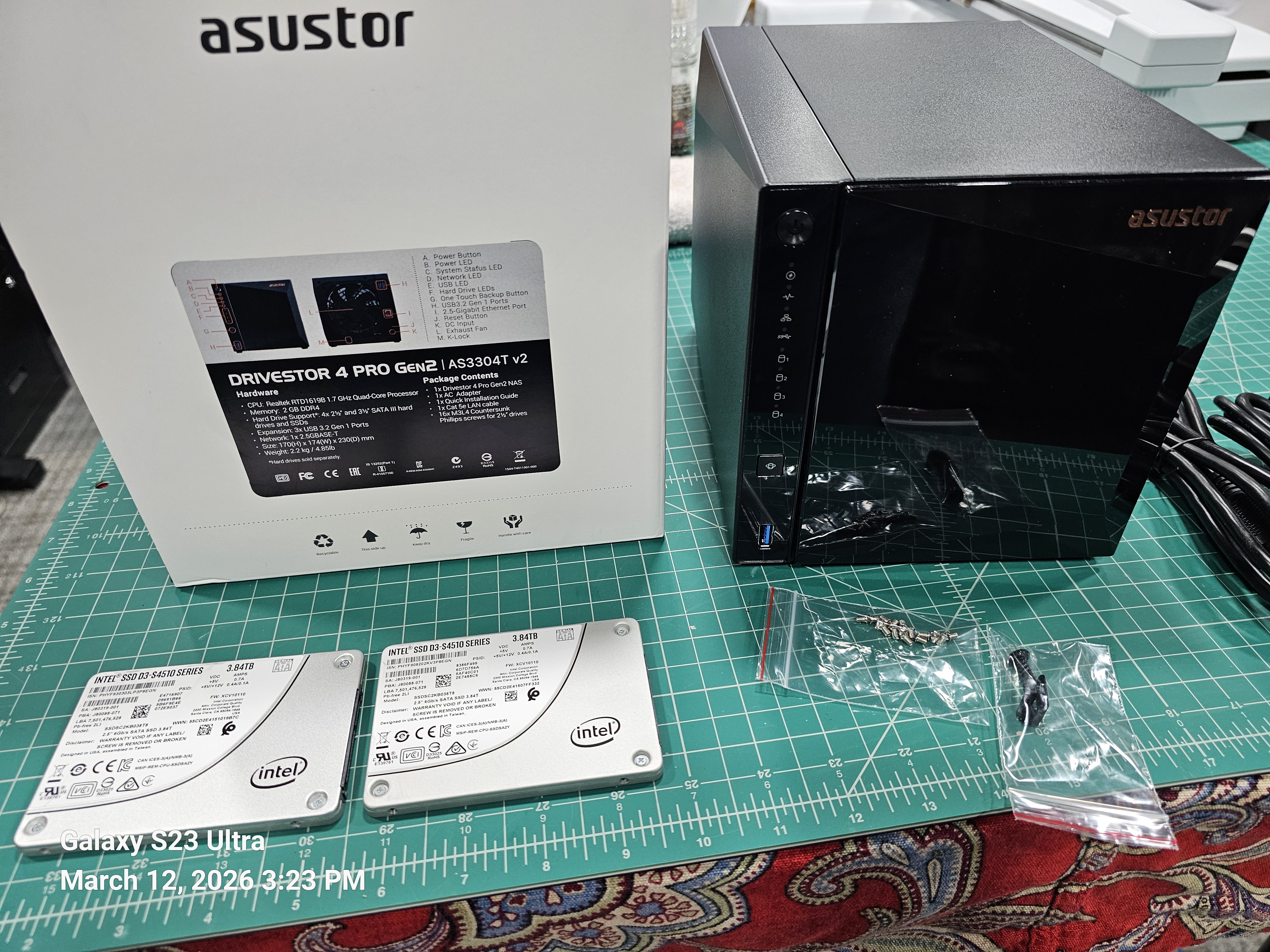
Product Photo
Initial Setup
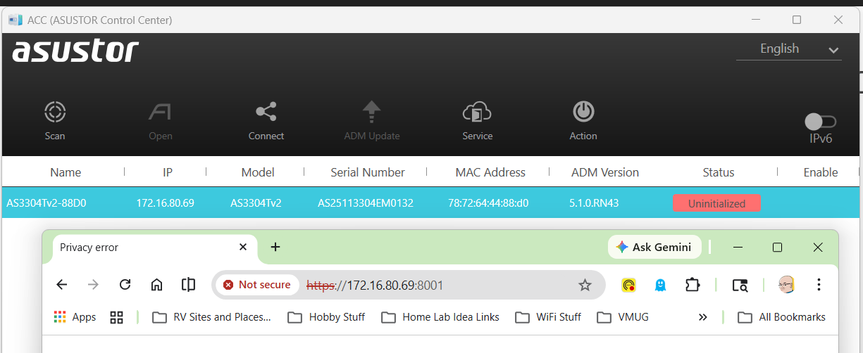
I plugged in the power and the network cable into the device and allowed it to get a DCHP address. To find the address assigned I downloaded and scanned my network with the ASUSTOR Control Center (acc.asustor.com). One I knew the IP address I went to it on port 8001.
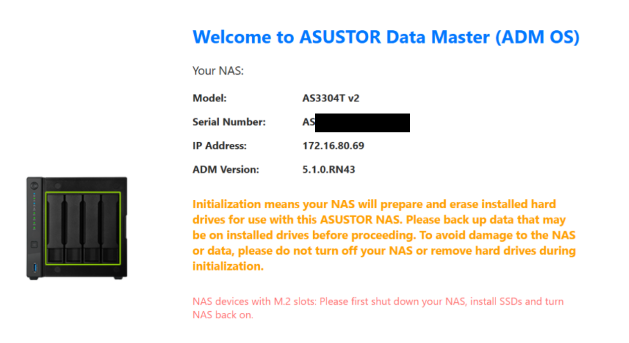
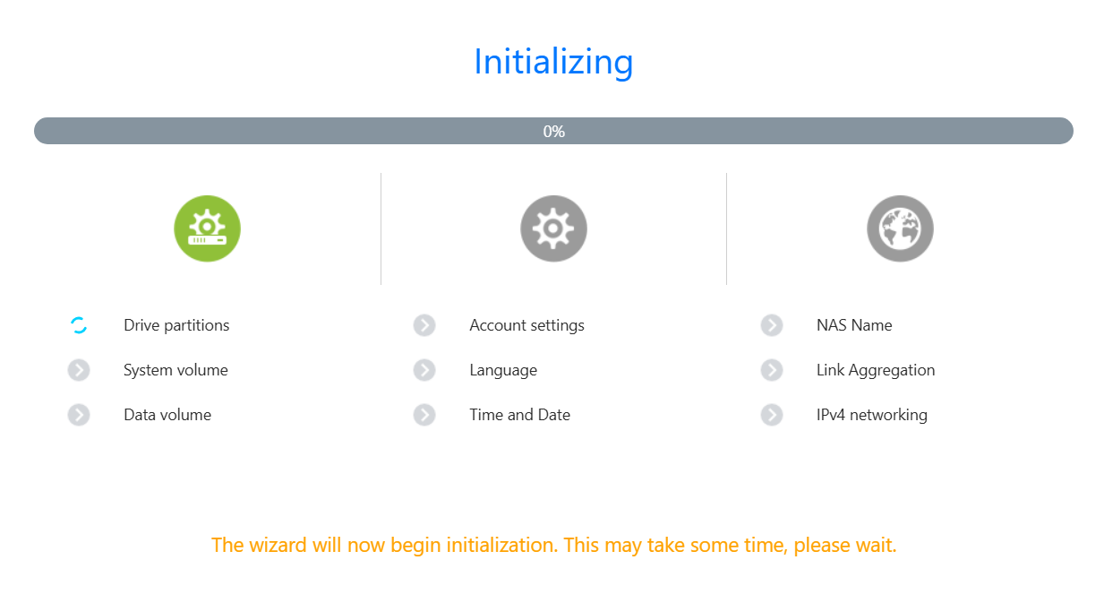
When I first entered the web interface I was welcomed by the main screen. One important note is the orange initialization statement. It notes your drive will be erased and a warning to backup your data.
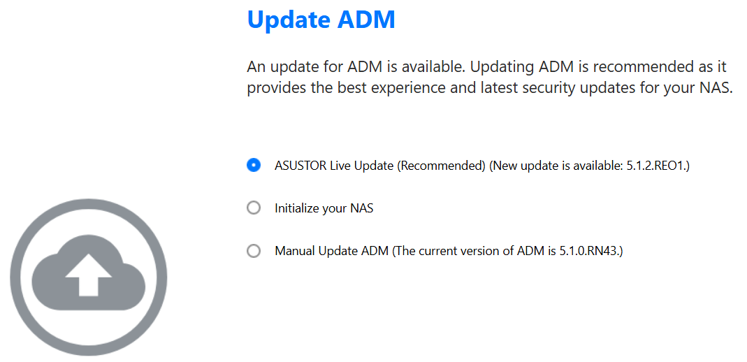
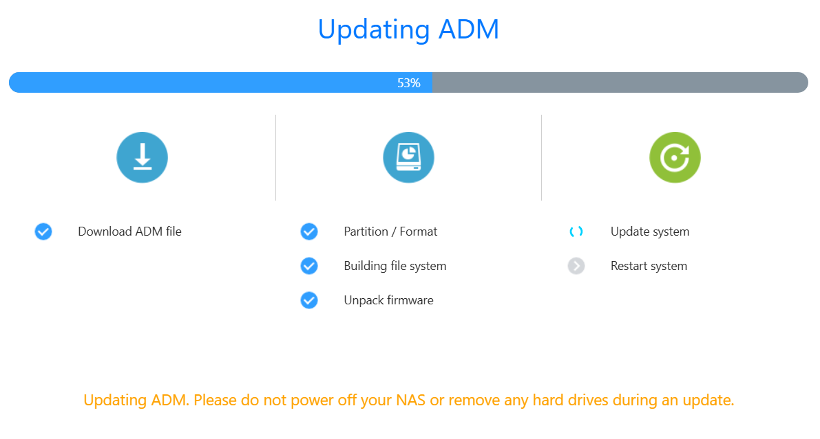
One thing I like about the initial setup is the ability to update the ADM (ASUSTOR Data Master) version. I allowed it to update as I was doing my install.
After I made all my selections, then ADM completes it pre-tasks.
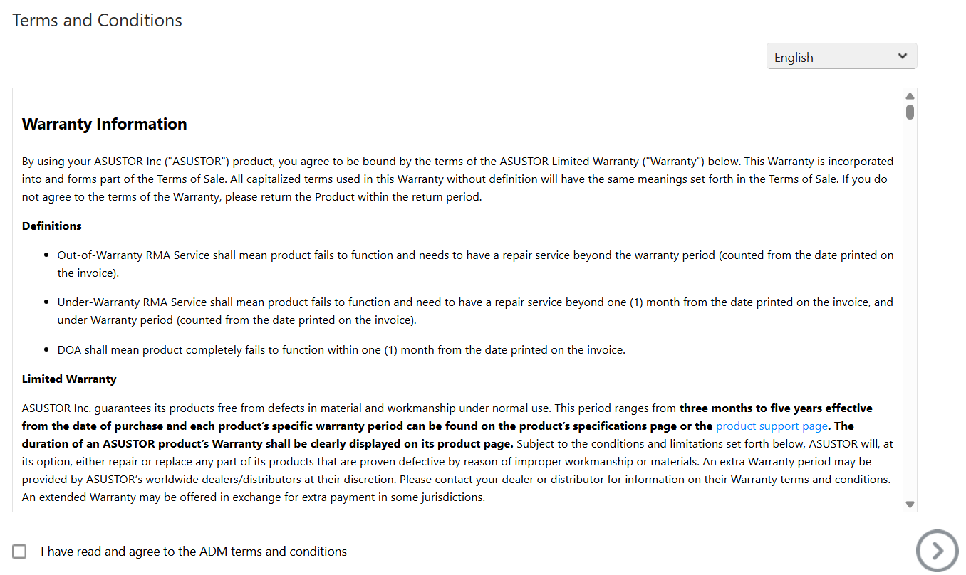
Next, the T&Cs are presented.
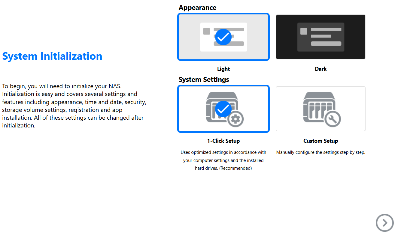
I get to choose my system appearance.
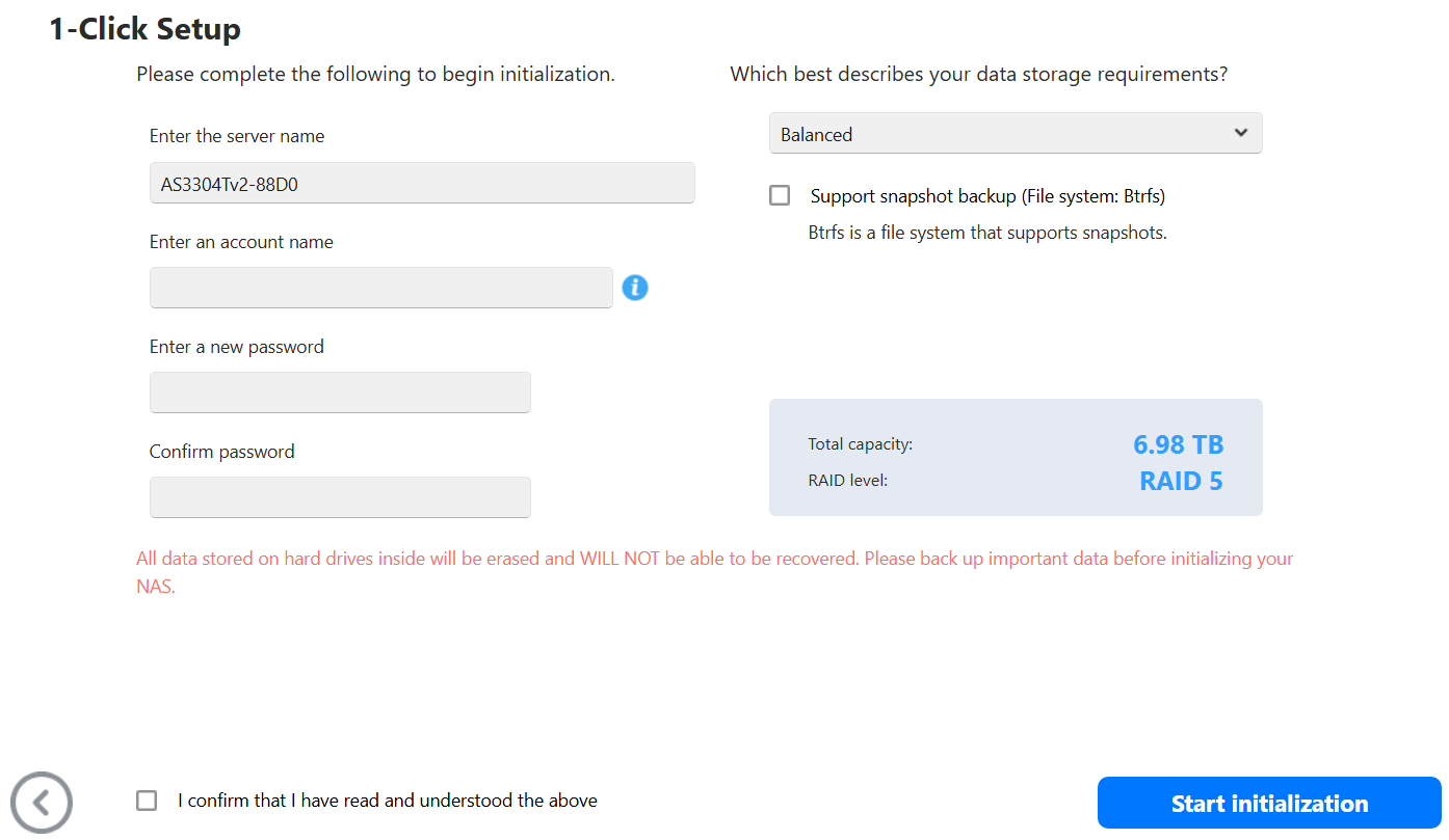
I entered my information.
The system does its final initialization.
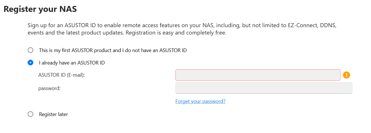
I enter in my ASUSTOR ID and then on next page put in your Contact information, region, and language
All done!
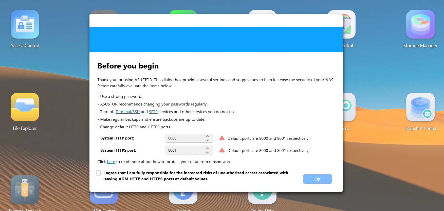
Back in the web interface, I’m prompted to adjust my http and https ports. I change them from the defaults of 8000 and 8001.
The ADM guide appears and it is a good way to learn where things are. I’m not going through all 6 steps but just know its a very hand tool.
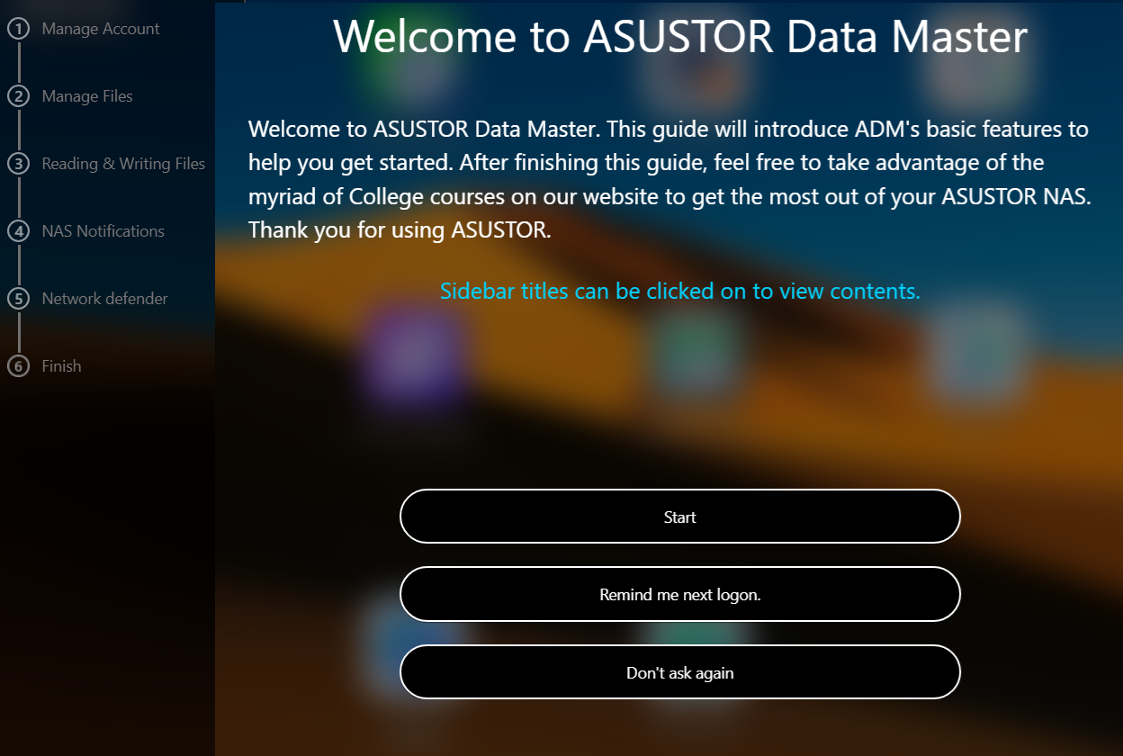
Here is what the first one looks like.
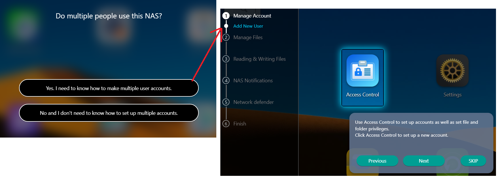
It actually takes you step by step.
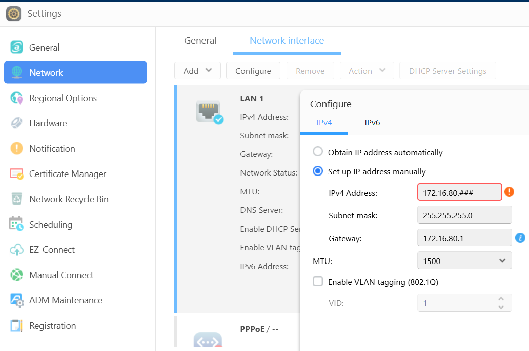
Once I exit the ADM guide, I first set up my network address. Settings > Network > change to manual IP > enter my IP and save it. The web interface reboots into the new IP. Additionally, I disabled IPv6.
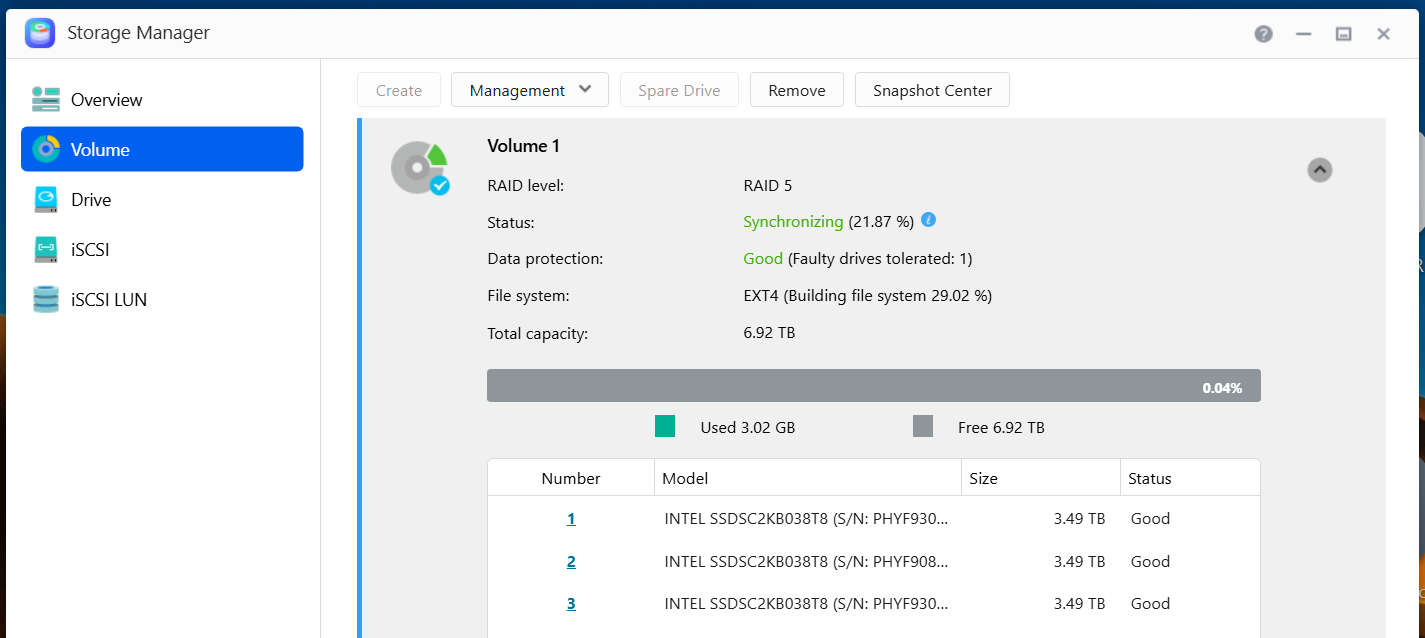
Next I go into the Storage Manager and validate my disks. It also gives me a status of the RAID 5 initialization.
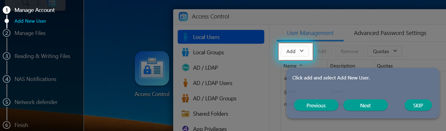
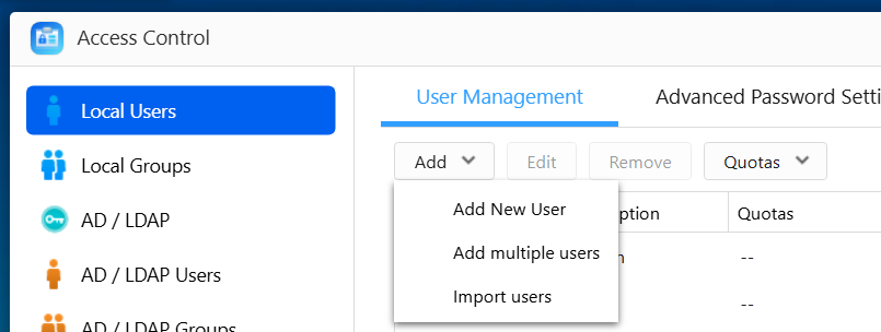
Then in Access Control I’ll setup a few user accounts.
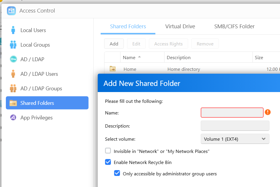
While in Access Control, I setup shared folder. The add shared folder window appears, I name my share, select access ‘by user’, choose the user and their access rights, chose to encrypt of not, and click on finish to complete the process.
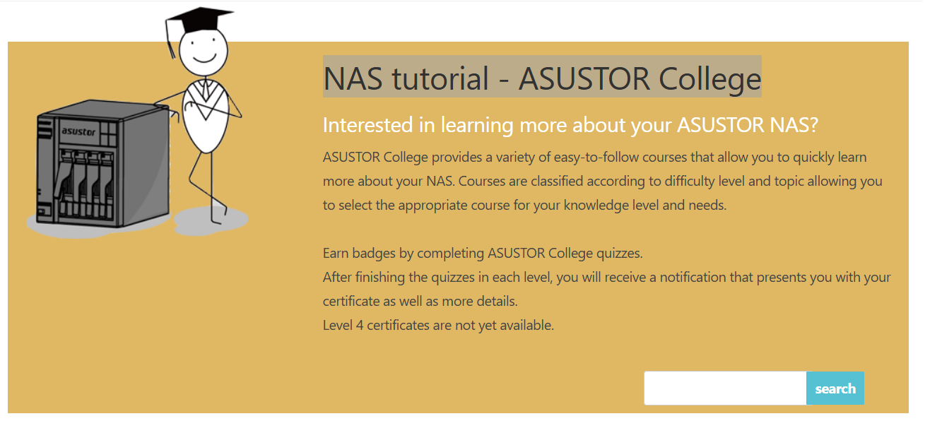
From my experience ADM is a very intuitive and easy to learn. Speaking of learning, ASUSTOR has a FREE NAS Tutorial that explains how to use it! I’ve used it quite a bit is worth a look.
While losing my original DRIVESTOR 2 Pro was a headache, the jump to the DRIVESTOR 4 Pro Gen 2 has been a massive silver lining. With the extra drive redundancy of RAID 5, I feel much more secure about our family’s digital files. It’s faster, quieter, and handles our school and work-from-home needs without breaking a sweat. If you’re looking for a NAS that balances power with a genuinely easy learning curve, ASUSTOR remains my top recommendation.
Using PowerShell to setup AV exceptions for Workstation 25H2u1 and Windows 11
Adding AV exceptions to your Workstation deployment on Windows 11 can really improve the overall performance. In this blog post I’ll share my exclusion script recently used on my environment.
NOTE: You cannot just cut, paste, and run the script below. There are parts of the script that have to be configured for the intended system.
What the script does.
- For Windows 11 users with Microsoft’s Virus & threat protection enabled this script will tell AV to not scan specific file types, folders, and processes related to VMware Workstation.
- It will ignore exceptions that already exist.
- It will display appropriate messages (Successful, or Already Exists) as it completes tasks.
What is the risk?
- Adding an exception (or exclusion) to antivirus (AV) software, while sometimes necessary for application functionality, significantly lowers the security posture of a device. The primary risk is creating a security blind spot where malicious code can be downloaded, stored, and executed without being detected.
- Use at your own risk. This code is for my personal use.
What will the code do?
It will add several exclusions listed below.
- File Type: Exclude these specific VMware file types from being scanned:
- .vmdk: Virtual machine disk files (the largest and most I/O intensive).
- .vmem: Virtual machine paging/memory files.
- .vmsn: Virtual machine snapshot files.
- .vmsd: Metadata for snapshots.
- .vmss: Suspended state files.
- .lck: Disk consistency lock files.
- .nvram: Virtual BIOS/firmware settings.
- Folder: Unique to my deployment it will exclude the following directories to prevent your antivirus from interfering with VM operations
- VMware Installation folder
- VM Storage Folders: Exclude the main directory where I store my virtual machines.
- Installation Folder: Exclude the VMware Workstation installation path ((default: C:\Program Files (x86)\VMware\VMware Workstation).
- Process:
- vmware.exe: The main Workstation interface.
- vmware-vmx.exe: The core process that actually runs each virtual machine.
- vmnat.exe: Handles virtual networking (NAT).
- vmnetdhcp.exe: Handles DHCP for virtual networks.
The Script
Under the section ‘#1. Define your exclusions ‘ is where I adapted this code to match my environment
# Check for Administrator privileges
if (-not ([Security.Principal.WindowsPrincipal][Security.Principal.WindowsIdentity]::GetCurrent()).IsInRole([Security.Principal.WindowsBuiltInRole]::Administrator)) {
Write-Warning "Please run this script as an Administrator."
break
}

# 1. Define your exclusions

# This is where you put in YOUR folder exclusions
$folders = @("C:\Program Files (x86)\VMware\VMware Workstation", "D:\Virtual Machines", "F:\Virtual Machines", "G:\Virtual Machines", "H:\Virtual Machines", "I:\Virtual Machines", "J:\Virtual Machines", "K:\Virtual Machines", "L:\Virtual Machines")

# These are the common process exclusions

$processes = @("C:\Program Files (x86)\VMware\VMware Workstation\vmware.exe", "C:\Program Files (x86)\VMware\VMware Workstation\x64\vmware-vmx.exe", "C:\Program Files (x86)\VMware\VMware Workstation\vmnat.exe", "C:\Program Files (x86)\VMware\VMware Workstation\vmnetdhcp.exe")

# These are the common extension exclusions

$extensions = @(".vmdk", ".vmem", ".vmsd", ".vmss", ".lck", ".nvram")

# Retrieve current settings once for efficiency
$currentPrefs = Get-MpPreference
Write-Host "Checking and applying Windows Defender Exclusions..." -ForegroundColor Cyan

# --- Validate and Add Folders ---
foreach ($folder in $folders) {
if ($currentPrefs.ExclusionPath -contains $folder) {
Write-Host "Note: Folder exclusion already exists, skipping: $folder" -ForegroundColor Yellow
} else {
Add-MpPreference -ExclusionPath $folder
Write-Host "Successfully added folder: $folder" -ForegroundColor Green
}
}

# --- Validate and Add Processes ---
foreach ($proc in $processes) {
if ($currentPrefs.ExclusionProcess -contains $proc) {
Write-Host "Note: Process exclusion already exists, skipping: $proc" -ForegroundColor Yellow
} else {
Add-MpPreference -ExclusionProcess $proc
Write-Host "Successfully added process: $proc" -ForegroundColor Green
}
}

# --- Validate and Add Extensions ---
foreach ($ext in $extensions) {
if ($currentPrefs.ExclusionExtension -contains $ext) {
Write-Host "Note: Extension exclusion already exists, skipping: $ext" -ForegroundColor Yellow
} else {
Add-MpPreference -ExclusionExtension $ext
Write-Host "Successfully added extension: $ext" -ForegroundColor Green
}
}

Write-Host "`nAll exclusion checks complete." -ForegroundColor Cyan
The Output
In the output below, when the script creates an item successfully it will show in green. If it detects a duplicate it will output a message in yellow. I ran the script with a .vmdk exclusion already existing to test it out.

When its complete the AV exclusions in Windows should looks similar to the partial screenshot below.
To view the exclusions, in Win 11 open ‘Virus & Threat Protection’ > Manage Settings > Under Exclusions chose ‘Add or remove exclusion’

Upgrading Workstation 25H2 to 25Hu1
Last February 26 2026 VMware released Workstation Pro 25H2u1. It’s an update that does repair a few bugs and security patches. In this blog I’ll cover how to upgrade it.
Helpful links
- Release Notes: VMware Workstation Pro 25H2u1 Release Notes
- Free Download: Download 25H2U1 < Recommend logging into support.broadcom.com first, then paste this link into your browser.
- Documentation: VMware Workstation Pro 25H2 Documentation
Meet the Requirements:
When installing/upgrading Workstation on Windows most folks seem to overlook the requirements for Workstation and just install the product. You can review the requirements here.
There are a couple of items folks commonly miss when installing Workstation.
- The number one issue is Processor Requirements for Host Systems . It’s either they have a CPU that is not supported or they simply did not enable Virtualization support in the BIOS.
- The second item is Microsoft Hyper-V enabled systems. Workstation supports a system with Hyper-V enabled but for the BEST performance its best to just disable these features.
- Next, if you’ve upgraded your OS but never reinstall Workstation, then its advised to uninstall then install Workstation.
- Lastly, if doing a fresh OS install ensuring drivers are updated and DirectX is at a supportable version.
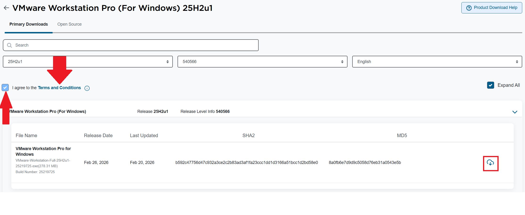
How to download Workstation
Download the Workstation Pro 25H2u1 for Windows. Make sure you click on the ‘Terms and Conditions’ AND check the box. Only then can you click on the download icon.
Choose your install path
Before you do a fresh install:
- Comply with the requirements
- For Accelerated 3D Graphics, ensure DirectX and Video card drivers are updated
- Review: Install Workstation Pro on a Windows Host
If you are upgrading Workstation, review the following:
- Ensure your environment is compatible with the requirements
- If you have existing VMs:
- Document your network settings
- Shut down your current version of Workstation
- Review: Upgrading Workstation Pro
Note: If you are upgrading the Windows OS or in the past have done a Windows Upgrade (Win 10 to 11), you must uninstall Workstation first, and then reinstall Workstation. More information here.
Upgrading Workstation 25H2 to 25Hu1
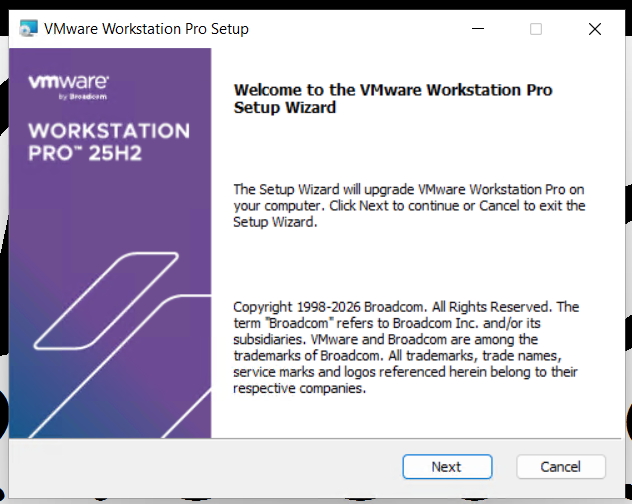
Run the download file, wait a min for it to confirm space requirements, then click Next
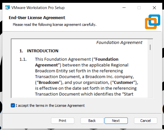
Accept the EULA.
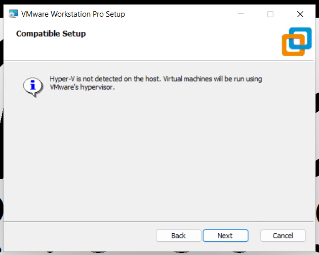
Compatible setup check
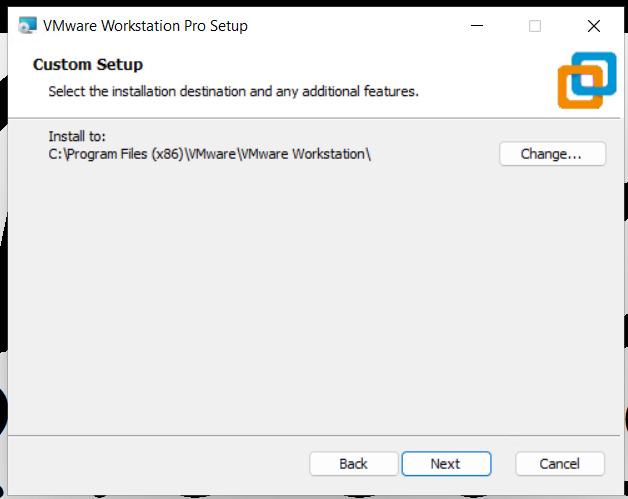
Confirm install directory
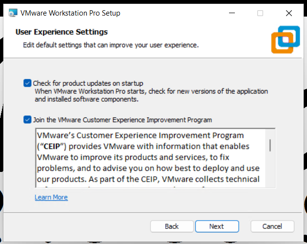
Check for updates and join the CEIP program.
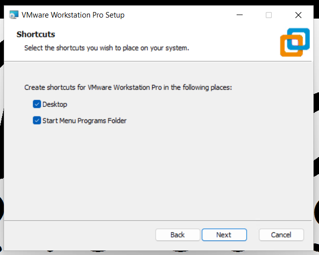
Allow it to create shortcuts
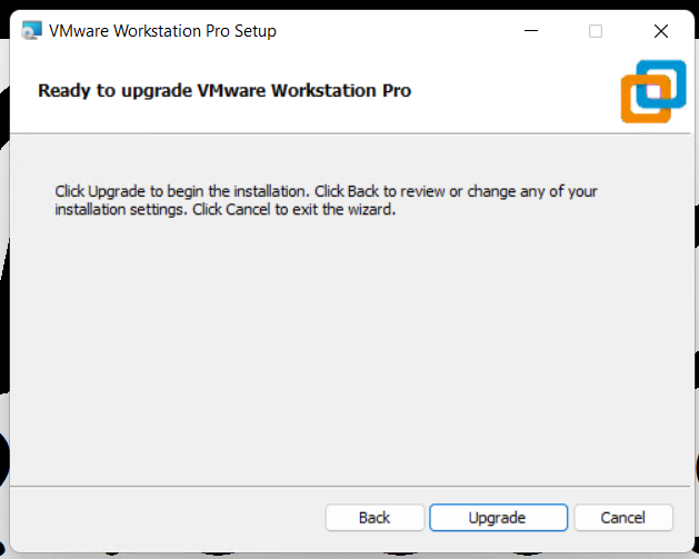
Click Upgrade to complete the upgrade
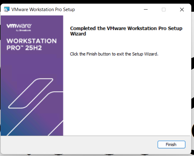
Click on Finish to complete the Wizard.
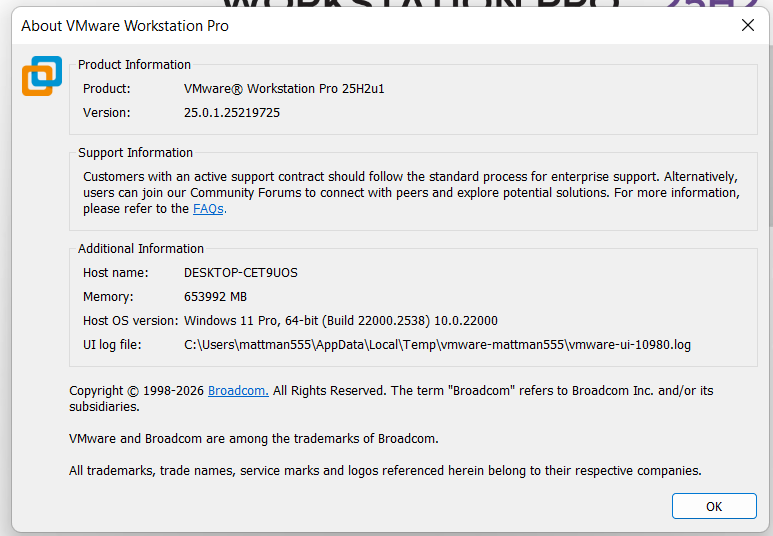
Lastly, check the version number of Workstation. Open Workstation > Help > About
My Silicon Treasures: Mapping My Home Lab Motherboards Since 2009
I’ve been architecting home labs since the 90s—an era dominated by bare-metal Windows Servers and Cisco products. In 2008, my focus shifted toward virtualization, specifically building out VMware-based environments. What began as repurposing spare hardware for VMware Workstation quickly evolved. As my resource requirements scaled, I transitioned to dedicated server builds. Aside from a brief stint with Gen8 enterprise hardware, my philosophy has always been “built, not bought,” favoring custom component selection over off-the-shelf rack servers. I’ve documented this architectural evolution over the years, and in this post, I’m diving into the the specific motherboards that powered my past home labs.
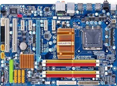
Gen 1: 2009-2011 GA-EP43-UD3L Workstation 7 | ESX 3-4.x
Back in 2009, I was working for a local hospital in Phoenix and running the Phoenix VMUG. I deployed a Workstation 7 Home lab on this Gigabyte motherboard. Though my deployment was simple, I was able deploy ESX 3.5 – 4.x with only 8GB of RAM and attach it to an IOMega ix4-200d. I used it at our Phoenix VMUG meetings to teach others about home labs. I found the receipt for the CPU ($150) and motherboard ($77), wow price sure have changed.
REF Link – Home Lab – Install of ESX 3.5 and 4.0 on Workstation 7
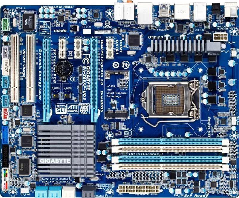
Gen2: 2011-2013 Gigabyte GA-Z68XP-UD3 Workstation 8 | ESXi 4-5
Gen1 worked quite well for what I needed but it was time to expand as my I started working for VMware as a Technical Account Manager. I needed to keep my skills sharp and deploy more complex home lab environments. Though I didn’t know it back then, this was the start of my HOME LABS: A DEFINITIVE GUIDE. I really started to blog about the plan to update and why I was making different choices. I ran into a very unique issues that even Gigabyte or Hitachi could figure out, I blogged about here.
Deployed with an i7-2600 ($300), Gigabyte GA-Z68XP-UD3 ($150), and 16GB DDR3 RAM
REF Link: Update to my Home Lab with VMware Workstation 8 – Part 1 Why
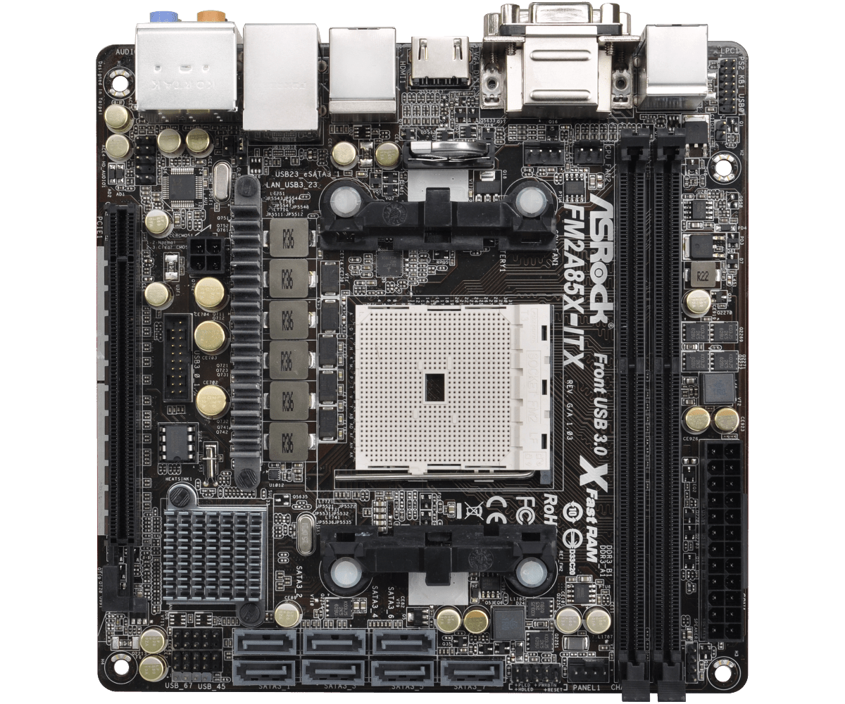
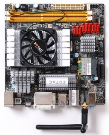
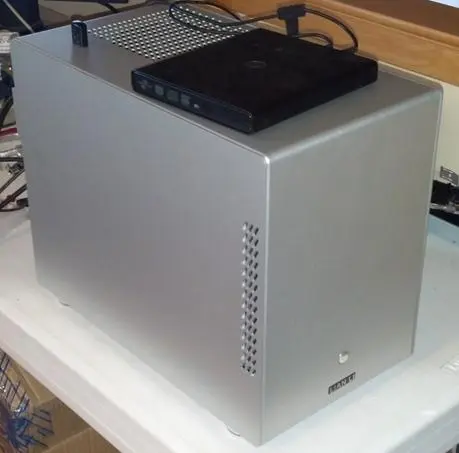
Gen2: Zotac M880G-ITX then the ASRock FM2A85X-ITX | FreeNAS Sever
Back in the day I needed better performance from my shared storage as the IOMega had reached its limits. Enter the short lived FreeNAS server to my home lab. Yes it did preform better but man it was full of bugs and issues. Some due to the Zotac Motherboard and some with FreeNAS. I was happy to be moving on to vSAN with Gen3.
REF: Home Lab – freeNAS build with LIAN LI PC-Q25, and Zotac M880G-ITX
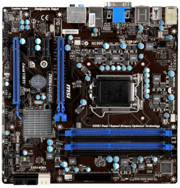
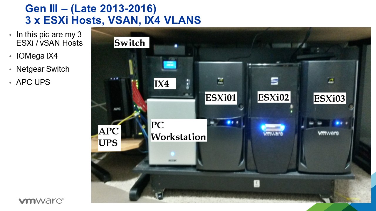
Gen3: 2012-2016 MSI Z68MA-G45 (B3) | ESXi 5-6
I needed to expand my home lab into dedicated hosts. Enter the MSI Z68MA-G45 (B3). It would become my workhorse expanding it from one server with the Gen 2 Workstation to 3 dedicated hosts running vSAN.
REF: VSAN – The Migration from FreeNAS
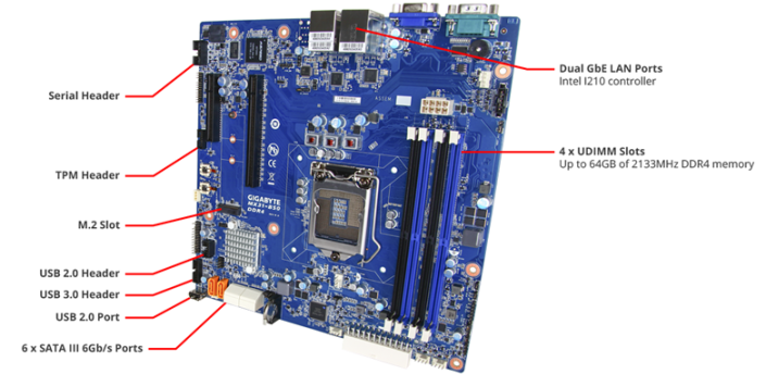
Gen4: 2016-2019 Gigabyte MX31-BS0
This mobo was used in my ‘To InfiniBand and beyond’ blog series. It had some “wonkiness” about its firmware updates but other then that it was a solid performer. Deployed with a E3-1500 and 32GB RAM
REF: Home Lab Gen IV – Part I: To InfiniBand and beyond!
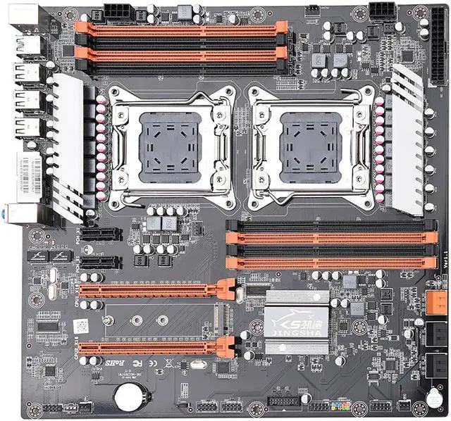
Gen 5: 2019-2020 JINGSHA X79
I had maxed out Gen 4 and really needed to expand my CPU cores and RAM. Hence the blog series title – ‘The Quest for More Cores!’. Deployed with 128GB RAM and Xeon E5-2640 v2 8 Cores it fit the bill. This series is where I started YouTube videos and documenting my builds per my design guides. Though this mobo was good for its design its lack of PCIe slots made it short lived.
REF: Home Lab GEN V: The Quest for More Cores! – First Look
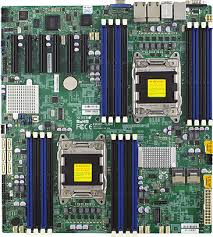
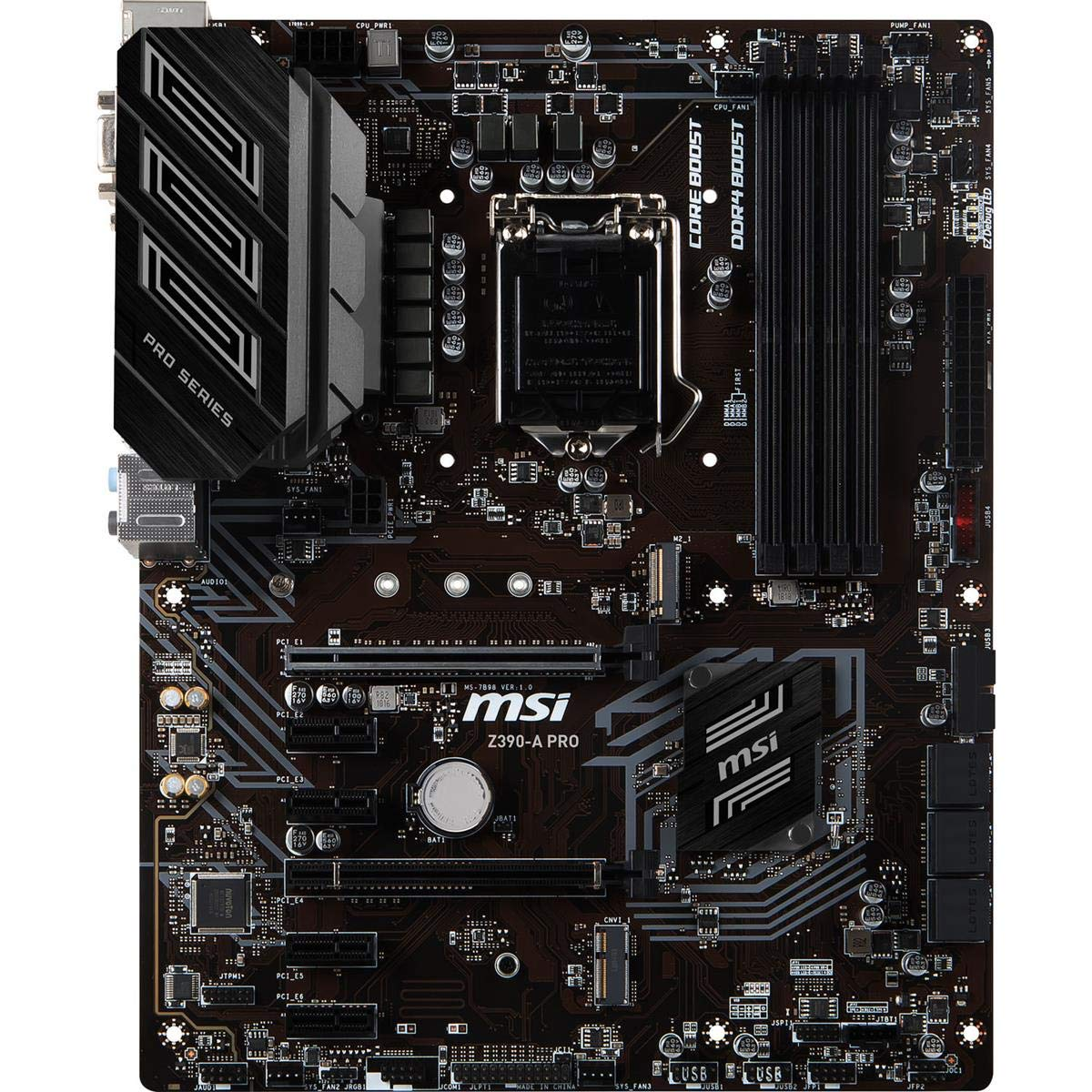
Gen 7: 2020-2023: Supermicro X9DRD-7LN4F-JBOD and the MSI PRO Z390-A PRO
Gen 5 motherboard fell short when I wanted to deploy and all flash vSAN based on NVMe. With this Supermicro motherboard I had no issues with IO and deploying it as all Flash vSAN. It also gathered the attention of Intel to which they offered me their Optane drives to create an All Flash Optane system. More on that in Gen 8.
The MSI motherboard was a needed update to my VMware Workstation system. I built it up as a Workstation / Plex server and it did this job quite well.
This generation is when I started to align my Gen#s to vSphere releases. Makes it much easier to track.
REF: Home Lab Generation 7: Updating from Gen 5 to Gen 7
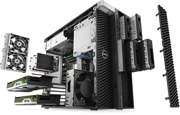
Gen 8: 2023-2024 Dell T7820 VMware Dedicated Hosts
With some support from Intel I was able to uplift my 3 x Dell T7820 workstations into a great home lab. They supplied Engineering Samples CPUs, RAM, and Optane Disks. Plus I was able to coordinate the distribution of Optane disks to vExperts Globally. It was a great homelab and I leaned a ton!
REF: Home Lab Generation 8 Parts List (Part 2)
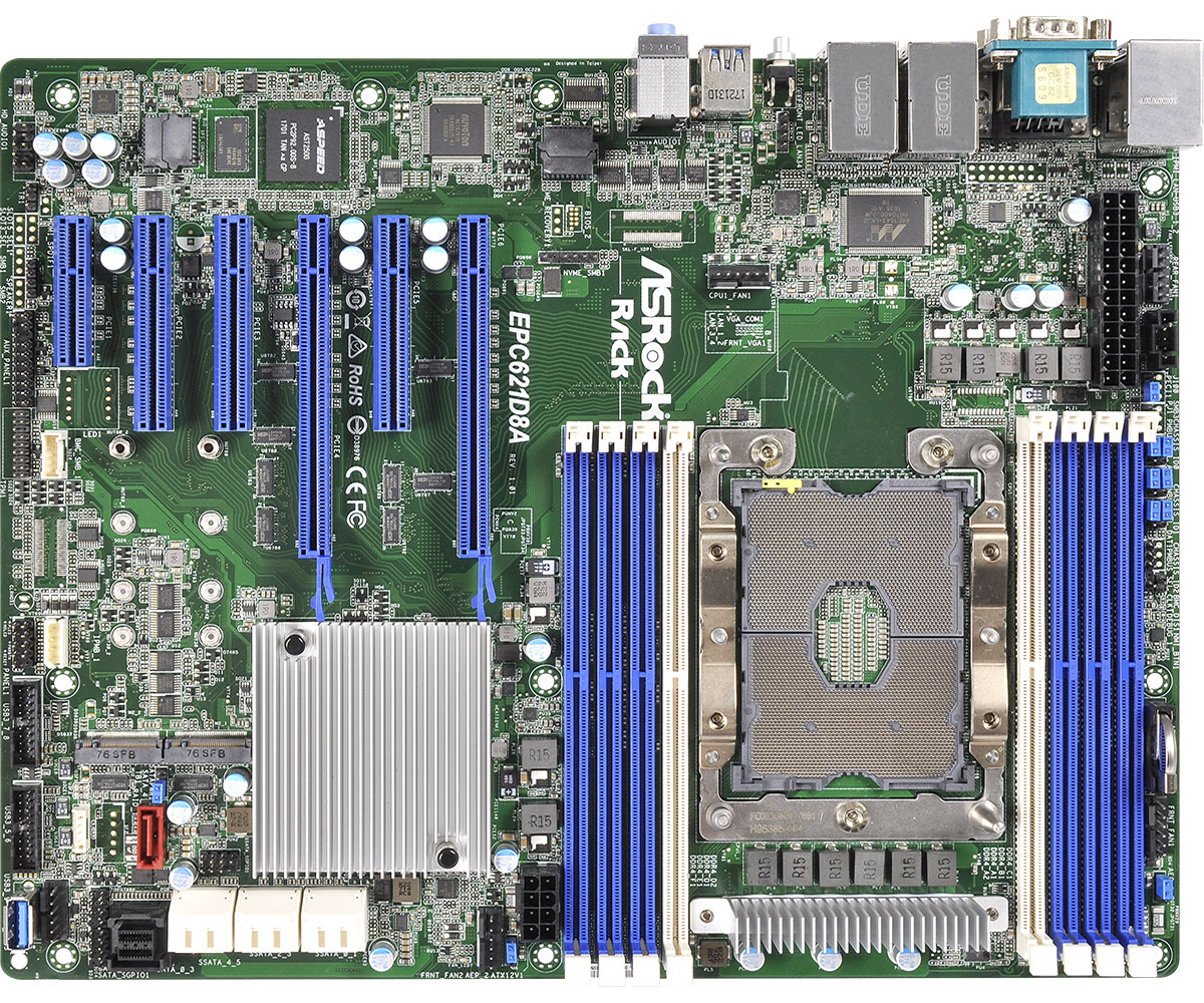
Gen 8-9: 2023-2026 ASRack Rock EPC621D8A VMware Workstation Motherboard
Evolving my Workstation PC I used this ASRack Rock motherboard. It was the perfect solution for running nested clusters of ESXi VMs with vSAN ESA. It was until most recently a really solid mobo and I even got it to run nested VCF 9 simple install.
REF: Announcing my Generation 8 Super VMware Workstation!
Gen 9: 2024 – Current
As of this date its still under development. See my Home Lab BOM for more information. However, I’m moving my home lab to only nested VCF 9 deployment on Workstation and not dedicated servers.
VMware Workstation Gen 9: Part 3 Windows Core Services and Routing
A big part of my nested VCF 9 environment relies on core services. Core services are AD, NTP, DHCP, and RAS. Core services are supplied by my Windows Server (aka AD230.nested.local). Of those services, RAS will enable routing between the LAN Segments and allow for Internet access. Additionally, I have a VM named DomainTools. DomainTools is used for testing network connectivity, SSH, WinSCP, and other tools. In this blog I’ll create both of these VMs and adapt them to work in my new VCF 9 environment.
Create the Window Server and establish core services
A few years back I published a Workstation 17 YouTube multipart series on how to create a nested vSphere 8 with vSAN ESA. Part of that series was creating a Windows Server with core services. For my VCF 9 environment I’ll need to create a new Windows server with the same core services. To create a similar Windows Server I used my past 2 videos: VMware Workstation 17 Nested Home Lab Part 4A and 4B.
Windows Server updates the VCF 9 environment
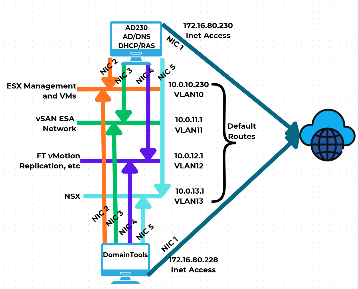
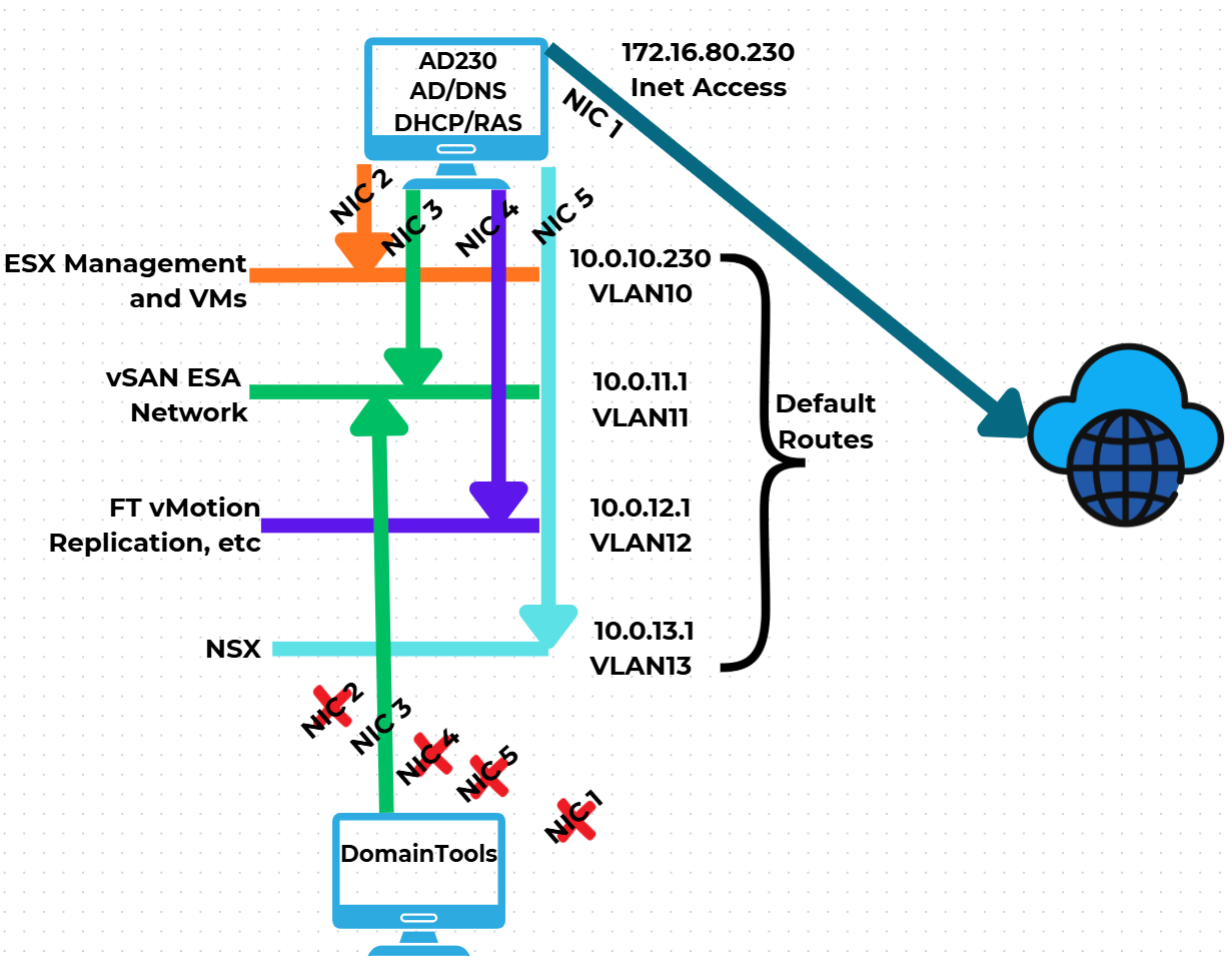
Now that I have established AD230 I need to update it to match the VCF 9 networks. I’ll be adding additional vNICs, attaching them to networks, and then ensuring traffic can route via the RAS service. Additionally, I created a new Windows 11 VM named DomainTools. I’ll use DomainTools for network connectivity testing and other functions. Fig-1 shows the NIC to network layout that I will be following.
(Fig-1)
Adjustments to AD230 and DomainTools
I power off AD230 and DomainTools. On both I add the appropriate vNICs and align them to the LAN segments. Next, I edit their VMware VM configuration file changing the vNICs from “e1000e” to “vmxnet3”.

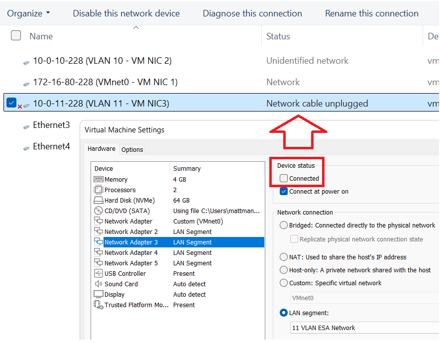
Starting with DomainTools for each NIC, I power it on, input the IPv4 information (IP Address, Subnet, VLAN ID), and optionally disable IPv6. The only NIC to get a Default Gateway is NIC1. TIP – To ID the NICs, I disconnect the NIC in the VM settings and watch for it to show unplugged in Windows Networking. This way I know which NIC is assigned to which LAN Segment. Additionally, in Windows Networking I add a verbose name to the NIC to help ID it.
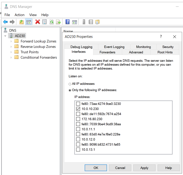
I make the same network adjustments to AD230 and I update its DNS service to only supply DNS from the 10.0.10.230 network adapter.
Once completed I do a ping test between all the networks for AD230 and DomainTools to validate IP Connectivity works. TIP – Use ipconfig at the CLI to check your adapter IP settings. If ping is not working there may be firewall enabled.
Setting up RAS on AD230
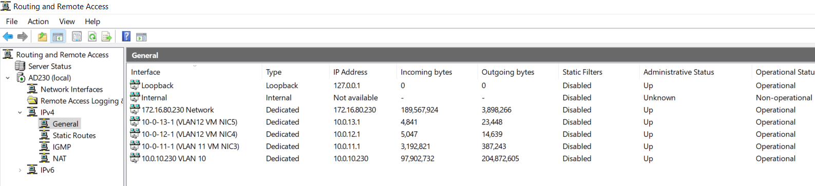
Once you have your network setup correctly validate that RAS has accepted your new adapters and their information. On AD230 I go in to RAS > IPv4 > General
I validate that my network adapters are present.
Looking ahead — RAS seemed to work right out of the box with no config needed. In all my testing below it worked fine, this may change as I advance my lab. If so, I’ll be sure to update my blog.
Next I need to validate routing between the different LAN Segments. To do this I’ll use the DomainTools VM to ensure routing is working correctly. You may notice in some of my testing results that VCF Appliances are present. I added this testing part after I had completed my VCF deployment.
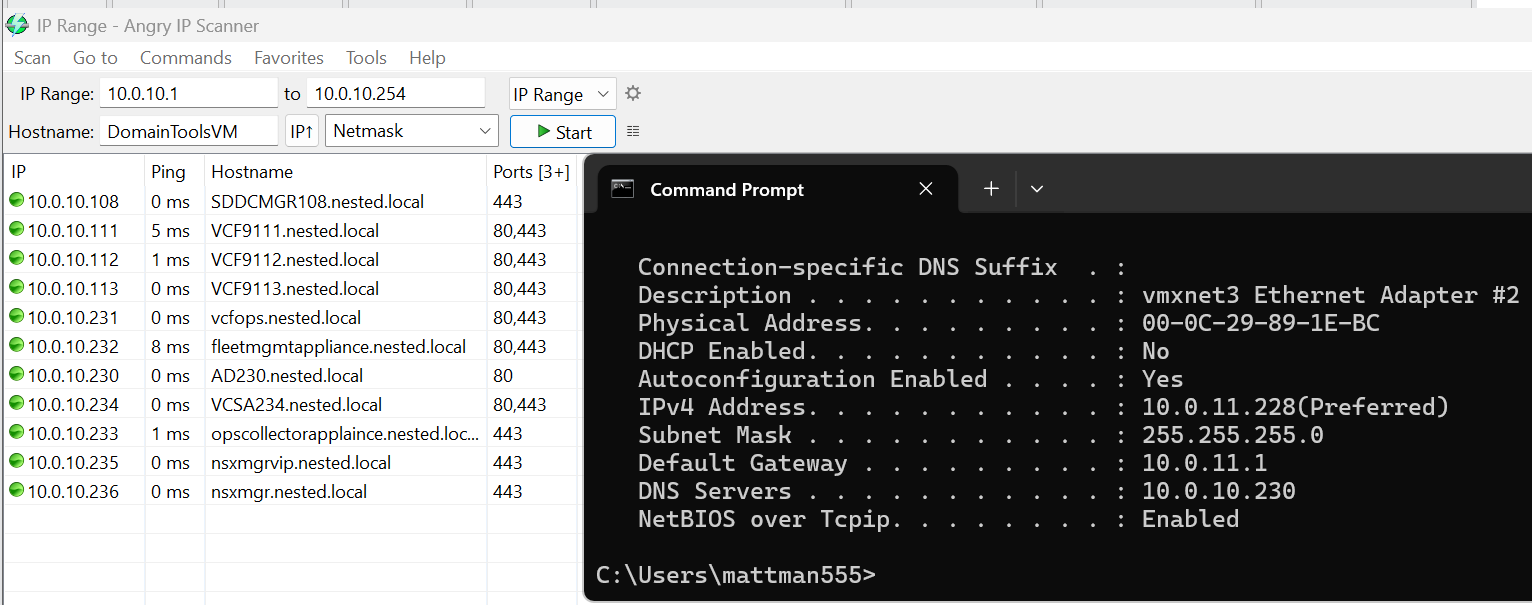
I need to test all of the VLAN networks. On the DomainTools VM, I disable each network adapter except for the one I want to test. In this case I disabled every adapter except for 10-0-11-228 (VLAN 11 – VM NIC3). I then add the gateway IP of 10.0.11.1 (this is the IP address assigned to my AD230 RAS server).
Next I do an ipconfig to validate the IP address, and use Angry IP Scanner to locate devices on the 10.0.10.x network. Several devices responded, plus resolving their DNS name, proving that DomainTools is successfully routing from the 11 network into the 10 network. I’ll repeat this process, plus do an internet check, on all the remaining networks.
Now that we have a stable network and core Window services established we are ready to move on to ESX Host Deployment and initial configuration.
Why your Home Lab needs a non-static port group.
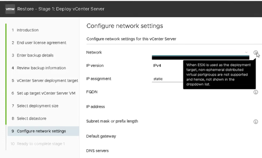
We’ve all been there, during a recovery or migration of a VCSA server we get the error – “Addition or reconfiguration of network adapters attached to non-ephemeral distributed virtual port groups is not supported.” But what does this mean and how do I prepare for this? In the blog post I’ll cover some of the basics and how I setup my home lab.

What does non-ephemeral and ephemeral mean?
- Non-ephemeral or static binding is a port group setting that guarantees a port in the vDS. Think of it like seats at a table and once a seat is assigned it’s always reserved for that assignment.
- Ephemeral or non-static binding will not guarantee a port in the switch. It’s kind of like first come first seated at the table, you leave the table someone else can take your spot.
- Of course you’d want to make sure your ESXi hosts and important VM’s like the VCSA appliance have a “reserved seat at the table” and this is why vDS port groups are static by default.
- See this KB for more information.
What are some of the impacts of not having a non-static port group?
- If you are doing an migration, or recovery of a VM you’ll sometimes end up at the ESXi Host Client.
- At some point during the network discovery process it’ll determine the target network is static bound.
- As an example, restoring a VCSA server if the vDS port group it’s using is static or non-ephemeral binding port group (vDS) then it will surely through the error.
How do I prepare my Home Lab?
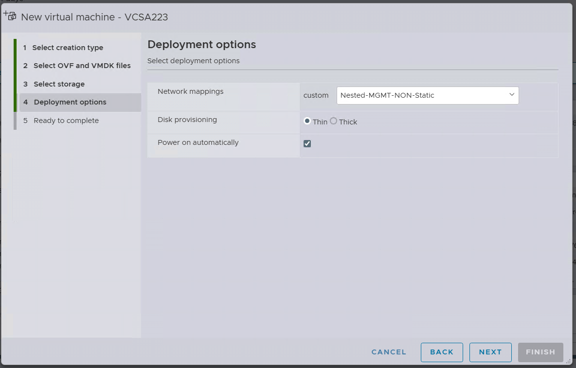
- Choice 1 – simply create a vDS Port Group with the Ephemeral – no binding setting that uses the same uplinks as the network I want to communicate on.
- Choice 2 – set your managment vDS Port Group to Ephemeral – no binding
- By doing one of these 2 ahead of time, this will allow the correct network to be chosen.
- Example – The screen shot below is a migration of a VCSA 8 server. When I get to step 4 I’m able to choose a non-static network. Had I not setup this port group ahead of time the migration would have been more difficult.
Want more information?
- Check out this design link that explains how VCF is assgined Static and Non-Static port groups
- Tech UnGlued did a good video around this topic.
VMware Workstation Gen 9: BOM2 P1 Motherboard upgrade (Failed Gigabyte board)
**Urgent Note ** The Gigabyte mobo in BOM2 initially was working well in my deployment. However, shortly after I completed this post the mobo failed. I was able to return it but to replace it the cost doubled. I replaced this mobo with a SuperMicro Board but am keeping this post up incase someone find it useful.
To take the next step in deploying a VCF 9 Simple stack with VCF Automation, I’m going to need to make some updates to my Workstation Home Lab. BOM1 simply doesn’t have enough RAM, and I’m a bit concerned about VCF Automation being CPU hungry. In this blog post I’ll cover some of the products I chose for BOM2.
Although my ASRock Rack motherboard (BOM1) was performing well, it was constrained by available memory capacity. I had additional 32 GB DDR4 modules on hand, but all RAM slots were already populated. I considered upgrading to higher-capacity DIMMs; however, the cost was prohibitive. Ultimately, replacing the motherboard proved to be a more cost-effective solution, allowing me to leverage the memory I already owned.
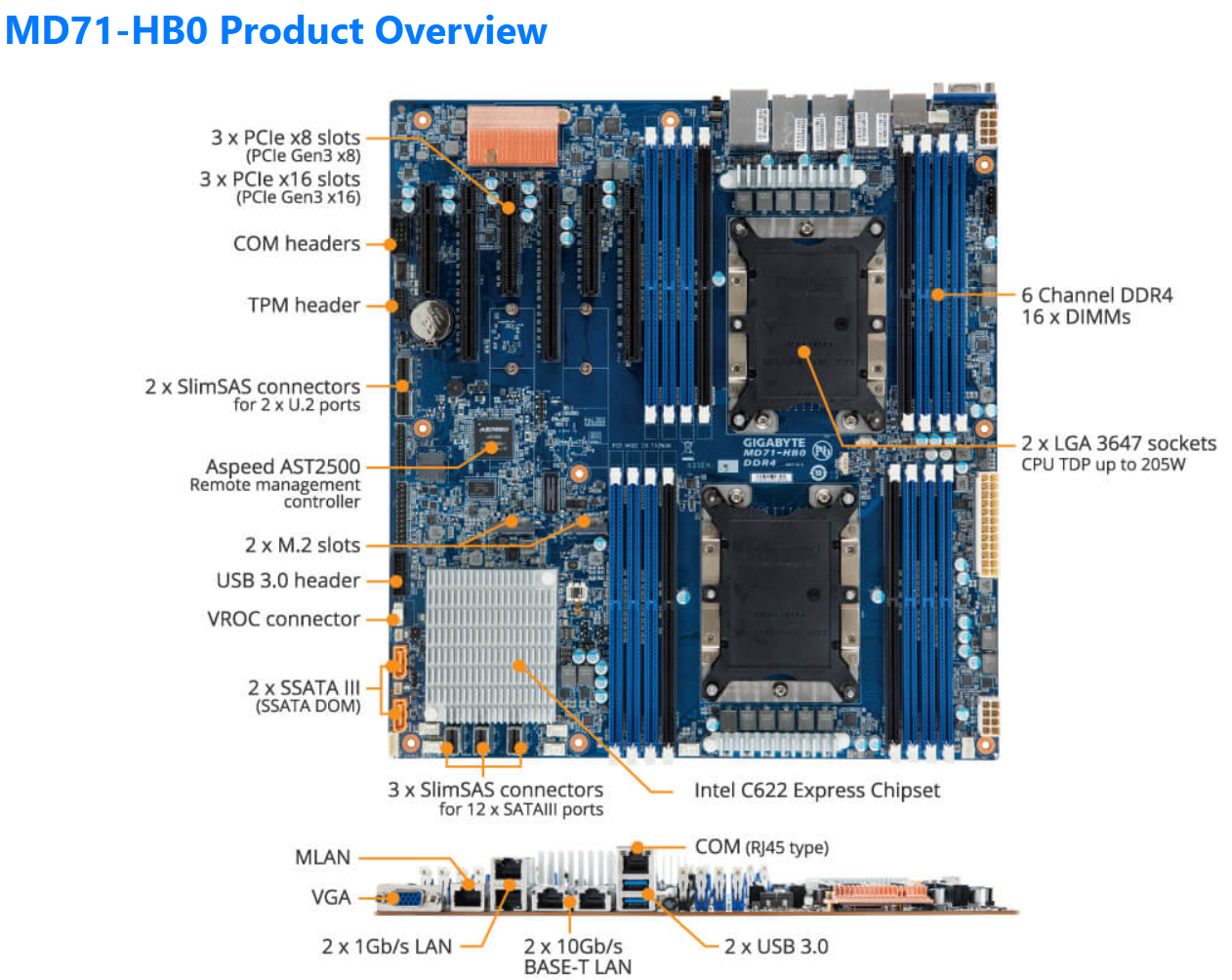
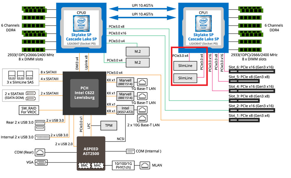
The mobo I chose was the Gigabyte Gigabyte MD71-HB0, it was rather affordable but it lacked PCIe bifurcation. Bifurcation is a feature I needed to support the dual NVMe disks into one PCIe slot. To overcome this I chose the RIITOP M.2 NVMe SSD to PCI-e 3.1 These cards essentially emulate a bifurcated PCIe slot which allows for the dual NVMe disks in a single PCIe slot.
The table below outlines the changes planned for BOM2. There was minimal unused products from the original configuration, and after migrating components, the updated build will provide more than sufficient resources to meet my VCF 9 compute/RAM requirements.
Pro Tip: When assembling new hardware, I take a methodical, incremental approach. I install and validate one component at a time, which makes troubleshooting far easier if an issue arises. I typically start with the CPUs and a minimal amount of RAM, then scale up to the full memory configuration, followed by the video card, add-in cards, and then storage. It’s a practical application of the old adage: don’t bite off more than you can chew—or in this case, compute.
| KEEP from BOM1 | Added to create BOM2 | UNUSED |
| Case: Phanteks Enthoo Pro series PH-ES614PC_BK Black Steel | Mobo: Gigabyte MD71-HB0 | Mobo: ASRack Rock EPC621D8A |
| CPU: 1 x Xeon Gold ES 6252 (ES means Engineering Samples) 24 pCores | CPU: 1 x Xeon Gold ES 6252 (ES means Engineering Samples) New net total 48 pCores | NVMe Adapter: 3 x Supermicro PCI-E Add-On Card for up to two NVMe SSDs |
| Cooler: 1 x Noctua NH-D9 DX-3647 4U | Cooler: 1 x Noctua NH-D9 DX-3647 4U | 10Gbe NIC: ASUS XG-C100C 10G Network Adapter |
| RAM: 384GB 4 x 64GB Samsung M393A8G40MB2-CVFBY 4 x 32GB Micron MTA36ASF4G72PZ-2G9E2 | RAM: New net total 640GB 8 x 32GB Micron MTA36ASF4G72PZ-2G9E2 | |
| NVMe: 2 x 1TB NVMe (Win 11 Boot Disk and Workstation VMs) | NVMe Adapter: 3 x RIITOP M.2 NVMe SSD to PCI-e 3.1 | |
| NVMe: 6 x Sabrent 2TB ROCKET NVMe PCIe (Workstation VMs) | Disk Cables: 2 x Slimline SAS 4.0 SFF-8654 | |
| HDD: 1 x Seagate IronWolf Pro 18TB | ||
| SSD: 1 x 3.84TB Intel D3-4510 (Workstations VMs) | ||
| Video Card: GIGABYTE GeForce GTX 1650 SUPER | ||
| Power Supply: Antec NeoECO Gold ZEN 700W | ||
PCIe Slot Placement:
For the best performance, PCIe Slot placement is really important. Things to consider – speed and size of the devices, and how the data will flow. Typically if data has to flow between CPUs or through the C622 chipset then, though minor, some latency is induced. If you have a larger video card, like the Super 1650, it’ll need to be placed in a PCIe slot that supports its length plus doesn’t interfere with onboard connectors or RAM modules.
Using Fig-1 below, here is how I laid out my devices.
- Slot 2 for Video Card. The Video card is 2 slots wide and covers Slot 1 the slowest PCIe slot
- Slot 3 Open
- Slot 4, 5, and 6 are the RIITOP cards with the dual NVMe
- Slimline 1 (Connected to CPU 1) has my 2 SATA drives, typically these ports are for U.2 drives but they also will work on SATA drives.
Why this PCIe layout? By isolating all my primary disks on CPU1 I don’t cross over the CPU nor do I go through the C622 chipset. My 2 NVMe disks will be attached to CPU0. They will be non-impactful to my VCF environment as one is used to boot the system and the other supports unimportant VCF VMs.
Other Thoughts:
- I did look for other mobos, workstations, and servers but most were really expensive. The upgrades I had to choose from were a bit constrained due to the products I had on hand (DDR4 RAM and the Xeon 6252 LGA-3647 CPUs). This narrowed what I could select from.
- Adding the RIITOP cards added quite a bit of expense to this deployment. Look for mobos that support bifurcation and match your needs. However, this combination + the additional parts were more than 50% less when compared to just updating the RAM modules.
- The Gigabyte mobo requires 2 CPUs if you want to use all the PCIe slots.
- Updating the Gigabyte firmware and BMC was a bit wonky. I’ve seen and blogged about these mobo issues before, hopefully their newer products have improved.
- The layout (Fig-1) of the Gigabyte mobo included support for SlimLine U.2 connectors. These will come in handy if I deploy my U.2 Optane Disks.
(Fig-1)
Now starts the fun, in the next posts I’ll reinstall Windows 11, performance tune it, and get my VCF 9 Workstation VMs operational.
