Test Lab
Home Lab Generation 7: Part 1 – Change Rational for software and hardware changes
Well its that time of year again, time to deploy new changes, upgrades, and add some new hardware. I’ll be updating my ESXi hosts and vCenter Server to the latest vSphere 7 Update 3a from 7U2d. Additionally, I’ll be swapping out the IBM 5210 JBOD for a Dell HBA330+ and lastly I’ll change my boot device to a more reliable and persistent disk. I have 3 x ESXi hosts with VSAN, vDS switches, and NSX-T. If you want to better understand my environment a bit better check out this page on my blog. In this 2 part blog I’ll go through the steps I took to update my home lab and some of the rational behind it.
There are two main parts to the blog:
- Part 1 – Change Rational for software and hardware changes – In this part I’ll explain some of my thoughts around why I’m making these software and hardware changes.
- Part 2 – Installation and Upgrade Steps – These are the high level steps I took to change and upgrade my Home lab
Part 1 – Change Rational for software and hardware changes:
There are three key changes that I plan to make to my environment:
- One – Update to vSphere 7U3a
- vSphere 7U3 has brought many new changes to vSphere including many needed features updates to vCenter server and ESXi. Additionally, there have been serval important bug fixes and corrections that vSphere 7U3 and 7U3a will address. For more information on the updates with vSphere 7U3 please see the “vSphere 7 Update 3 – What’s New” by Bob Plankers. For even more information check out the release notes.
- Part of my rational in upgrading is to prepare to talk with my customers around the benefits of this update. I always test out the latest updates on Workstation first then migrate those learnings in to Home Lab.
- Two – Change out the IBM 5210 JBOD
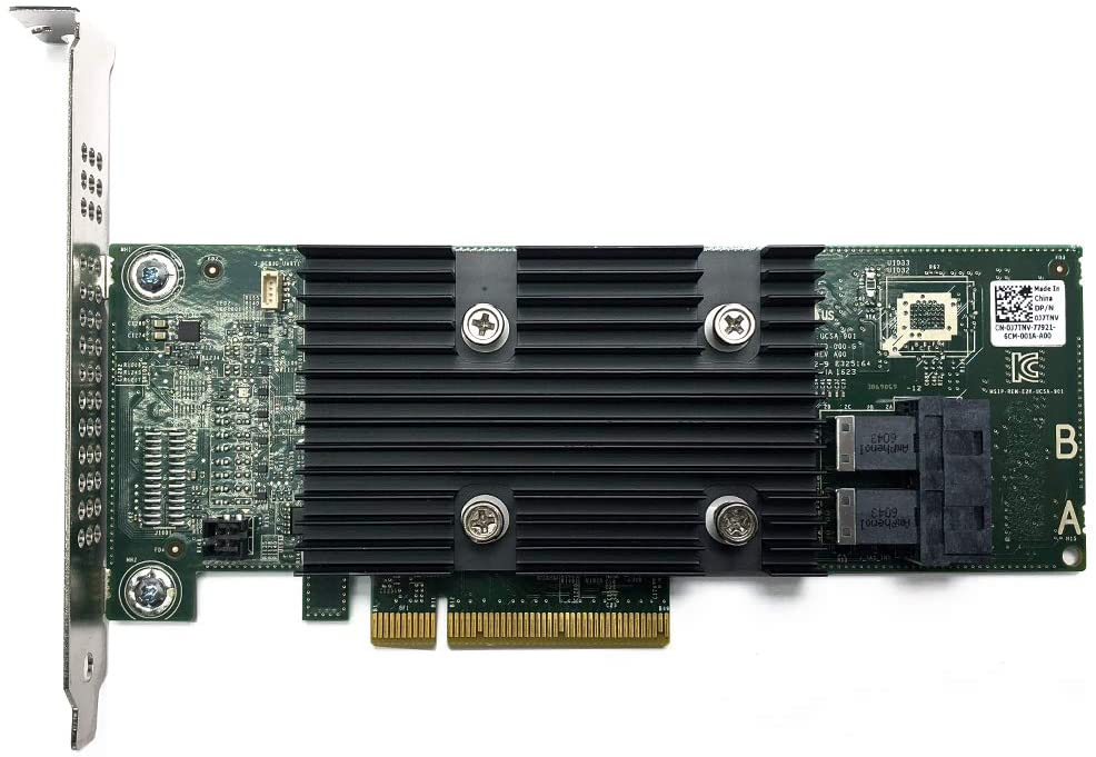
- The IBM 5210 JBOD is a carry over component from my vSphere 6.x vSAN environment. It worked well with vSphere 6.x and 7U1. However, starting in 7U2 it started to exhibit stuck IO issues and the occasional PSOD. This card was only certified with vSphere/vSAN 6.x and at some point the cache module became a requirement. My choices at this point are to update this controller with a cache module (~$50 each) and hope it works better or make a change. In this case I decided to make a change to the Dell HBA330 (~$70 each). The HBA330 is a JBOD controller that Dell pretty much worked with VMware to create for vSAN. It is on the vSphere/vSAN 7U3 HCL and should have a long life there too. Additionally, the HBA330 edge connectors (Mini SAS SFF-8643) line up with the my existing SAS break-out cables. When I compare the benefits of the Dell HBA330 to upgrading the cache module for the IBM 5210 the HBA330 was the clear choice. The trick is finding a HBA330 that is cost effective and comes with a full sized slot cover. Its a bit tricky but you can find them on eBay, just have to look a bit harder.
- Three – Change my boot disk
- Last September-2021, VMware announced boot from USB is going to change and customers were advised to plan ahead for these upcoming changes. My current hosts are using cheap SanDisk USB 64GB memory sticks. Its something I would never recommend for a production environment, but for a Home Lab these worked okay. I originally chose them during my Home Lab Gen 5 updates as I need to do testing with USB booted Hosts. Now that VMware has deprecated support for USB/SD devices it’s time to make a change. Point of clarity: the word deprecated can mean different things to different people. However, in the software industry deprecated means “discourage the use of (something, such as a software product) in favor of a newer or better alternative”. vSphere 7 is in a deprecated mode when it comes to USB/SD booted hosts, they are still supported, and customers are highly advised to plan ahead. As of this writing, legacy (legacy is a fancy word for vSphere.NEXT) USB hosts will require a persistent disk and eventually (Long Term Supported) USB/SD booted hosts will no longer be supported. Customers should seek guidance from VMware when making these changes.

-
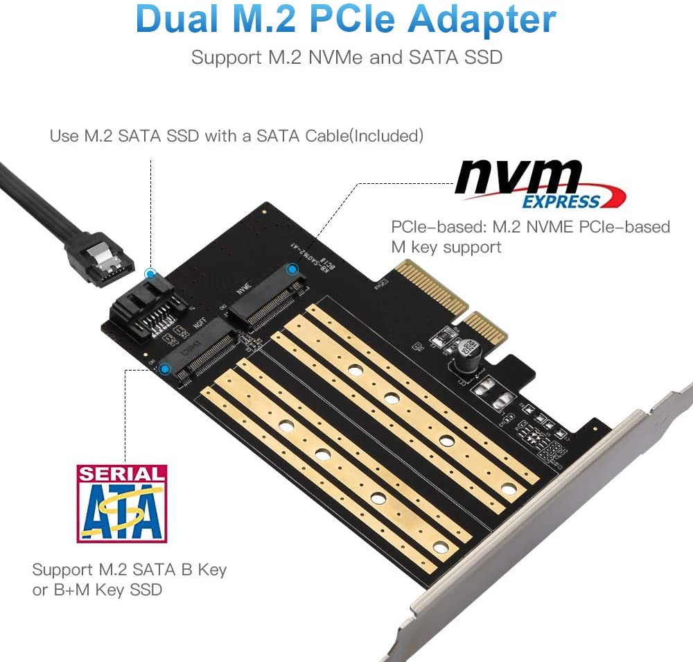
- The requirement to be in a “Long Term Supported” mode is to have a ESXi host be booted from HDD, SSD, or a PCIe device. In my case, I didn’t want to add more disks to my system and chose to go with a PCIe SSD/NVMe card. I chose this PCIe device that will support M.2 (SATA SSD) and NMVe devices in one slot and I decided to go with a Kingston A400 240G Internal SSD M.2 as my boot disk. The A400 with 240GB should be more than enough to boot the ESXi hosts and keep up with its disk demands going forward.

Final thoughts and a important warning. Making changes that affect your current environment are never easy but are sometimes necessary. With a little planning it can make the journey a bit easier. I’ll be testing these changes over the next few months and will post up if issues occur. However, a bit of warning – adding new devices to an environment can directly impact your ability to migrate or upgrade your hosts. Due to the hardware decisions I have made a direct ESXi upgrade is not possible and I’ll have to back out my current hosts from vCenter Server plus other software and do a new installation. However, those details and more will be in Part 2 – Installation and Upgrade Steps.
Opportunity for vendor improvement – If backup vendors like Synology, asustor, Veeam, Veritas, naviko, and Arcoins could really shine. If they could backup and restore a ESXi host to dislike hardware or boot disks this would be a huge improvement for VI Admin, especially when they have tens of thousands of hosts the need to change from their USB to persistent disks. This is not a new ask, VI admins have been asking for this option for years, now maybe these companies will listen as many users and their hosts are going to be affected by these upcoming requirements.
Quick NAS Topics: USB WiFi on the DRIVESTOR 2 Pro
During this Quick NAS Topic I review how to install and test a supported USB WiFi Network device into the DRIVESTOR 2 Pro.
** Products / Links Seen in this Video **
DRIVESTOR 2 PRO
asustor – https://www.asustor.com/en/product?p_id=72 and https://www.asustor.com/datasheet?p_id=72
OR Amazon – https://www.amazon.com/Asustor-Drivestor-Pro-AS3302T-Attached/dp/B08ZD7R72P
ASUS USB-AC56 https://www.asus.com/Networking-IoT-Servers/Adapters/All-series/USBAC56/
** Other Links **
https://www.asustor.com/service/compatibility
https://www.asustor.com/service/wifi?id=wifi
https://downloadgb.asustor.com/download/docs/User_Guide/ADM40/ASUSTOR_NAS_USER_GUIDE_ENU_4.0.0.0304.pdf
https://www.asustor.com/online/College
More details go to: vmexplorer.com
FIX for Netgear Orbi Router / Firewall blocks additional subnets
**2021-NOV Update** With the release of Orbi Router Firmware Version V2.7.3.22 the telnet option is no longer available in the debug menu. This means the steps below will not work unless you are a earlier router firmware version. I looked for other Orib solutions but didn’t find any. However, I solved this issue by using an additional firewall using NAT between VLAN74 and VLAN 75. If you find an Orbi solution, please post a comment and I’ll be glad to update this blog.
Last April 2019 I decided to update my home network with the Orbi WiFi System (RBK50) AC3000 by Netgear. My previous Netgear Wifi router worked quite well but I really needed something to support multiple locations seamlessly.
The Orbi Mesh has a primary device and allows for satellites to be connected to it. It creates a Wifi mesh that allows devices to go from room to room or building to building seamlessly. I’ve had it up for a while now and its been working out great – that is until I decided to ask it to route more than one subnet. In this blog I’ll show you the steps I took to over come this feature limitation but like all content on my blog this is for my reference. Use at your own risk.
To understand the problem we need to first understand the network layout. My Orbi Router is the Gateway of last resort and it supplies DHCP and DNS services. In my network I have two subnets which are untagged VLANS known as VLAN 74 – 172.16.74.x/24 and VLAN 75 – 172.16.75.x/24. VLAN 74 is used by my home devices and VLAN 75 is where I manage my ESXi hosts. I have enabled RIP v2 on the Orbi and on the Dell 6224 switch. The routing tables are populated correctly, and I can ping from any internal subnet to any host without issue, except when the Orbi is involved.

Issue: Hosts on VLAN 75 are not able to get to the internet. Hosts on VLAN 75 can resolve DNS names (example: yahoo.com) but it cannot ping any host on the Inet. Conversely, VLAN 74 can ping Inet hosts and get to the internet. I’d like for my hosts on VLAN 75 to have all the same functionally as my hosts on VLAN 74.

Findings: By default, the primary Orbi router is blocking any host that is not on VLAN 74 from getting to the INET. I believe Netgear enabled this block to limit the number of devices the Orbi could NAT. I can only guess that either the router just can’t handle the load or this was a maximum Netgear tested it to. I found this firewall block out by logging into the CLI of my Orbi and looking at the IPTables settings. There I could clearly see there was firewall rule blocking hosts that were not part of VLAN 74.
Solution: Adjust the Orbi to allow all VLAN traffic (USE AT YOUR OWN RISK)
- Enable Telnet access on your Primary Orbi Router.
- Go to http://{your orbi ip address}/debug.htm
- Choose ‘Enable Telnet’ (**reminder to disable this when done**)
- Telnet into the Orbi Router (I just used putty)
- Logon as root using your routers main password
- I issued the command ‘iptables -t filter -L loc2net’. Using the output of this command I can see where line 5 is dropping all traffic that is not (!) VLAN74.

- Let’s remove this firewall rule. The one I want to target is the 5th in the list, yours may vary. This command will remove it ‘iptables -t filter -D loc2net 5’
- NOTES:
- Router Firmware Version V2.5.1.16 (Noted: 10.2020) — It appears that more recent firmware updates have changed the targeting steps. I noticed in Router Firmware Version V2.5.1.16 I had to add 2 to the targeted line number to remove it with the ip tables command. This my vary for the device that is being worked on.
- Router Firmware Version V2.5.2.4 (Noted: Jan-2021) — It appears the targeting for steps are now fixed in this version.
- Again, as with all my posts, blogs, and videos are for my records and not for any intended purpose.
- Next, we need to clean up some post routing issues ‘iptables -t nat -I POSTROUTING 1 -o brwan -j MASQUERADE’
- A quick test and I can now PING and get to the internet from VLAN 75
- Disconnect from Telnet and disable it on your router.
Note: Unfortunately, this is not a permanent fix. Once you reboot your router the old settings come back. The good news is, its only two to three lines to fix this problem. Check out the links below for more information and a script.
Easy Copy Commands for my reference:
iptables -t filter -L loc2net
iptables -t filter -D loc2net 7 << Check this number
iptables -t nat -I POSTROUTING 1 -o brwan -j MASQUERADE
If you like my ‘no-nonsense’ blog articles that get straight to the point… then post a comment or let me know… Else, I’ll start writing boring blog content.
REF:
No web interface on a Dell PowerConnect 6224 Switch
I picked up a Dell Powerconnect 6224 switch the other day as my older Netgear switch (2007) finally died. After connecting via console cable (9600,8,1,none) I updated the Firmware image to the latest revision. I then followed the “Dell Easy Setup Wizard”, which by the way stated the web interface will work after the wizard is completed. After completing the easy wizard I opened a browser to the switch IP address which failed. I then pinged the switch IP address, yep it is replying. Next, rebooted the switch – still no web interface connection.
How did I fix this?
1- While in the console, entered into config mode, and issued the following command.
console(config)#ip http server
2- Next I issued a ‘show run’ to ensure the command was present
console#show run
!Current Configuration:
!System Description “PowerConnect 6224, 3.3.18.1, VxWorks 6.5”
!System Software Version 3.3.18.1
!Cut-through mode is configured as disabled
!
configure
stack
member 1 1
exit
ip address 172.16.74.254 255.255.255.0
ip default-gateway 172.16.74.1
ip http server
username “admin” password HASHCODE level 15 encrypted
snmp-server community public rw
exit
3 – This time I connected to the switch via a browser without issue.

4 – Finally, saved the running-configuration
console#copy running-config startup-config
This operation may take a few minutes.
Management interfaces will not be available during this time.
Are you sure you want to save? (y/n) y
Configuration Saved!
console#
Summary: These were some pretty basic commands to get the http service up and running, but I’m sure I’ll run into this again and I’ll have this blog to refer too. Next, I’m off to setup some VLANs and a few static routes.
If you like my ‘no-nonsense’ blog articles that get straight to the point… then post a comment or let me know… Else, I’ll start writing boring blog content.
Gigabyte MX31-BS0 Firmware / BIOS update for MergePoint Embedded Management Software and Motherboard
** Blog Updates / Notes **
I wrote this post when I first got my MX31-BS0 (2017), since then I have updated my BIOS several times using this process. Here are my notes around my most recent update experiences and blog comments.
- 07/2019 – Updated 1 host with MX-31BS0 BIOS from R10 to R11 and MergePoint EMS 8.73 to 8.85. This update didn’t go smooth and I cannot recommend it.
- Why did I update — I recently installed Java 9 and the vKVM under EMS 8.73 would not work. After installing R11/8.85 Java 9 seemed to work but I had issues
- Notes / Issues:
- Noted EMS 8.85 Changes: I didn’t dig in deep but the install log screen got a new look, and all the rest of the screens seemed to be the same. I had some random quirkiness (as stated int he blog post below) during the update, but nothing out of the ordinary.
- vKVM/vMedia Issues:
- EMS 8.85 with the vKVM or the vMedia would disconnect upon reboot of the host OR it would do this randomly. This is with the ‘Keep PHY link up’ enabled.
- Tested on a system with Java 8 and had the same results
- Downgraded to EMS 8.73 with BIOS R11 all issues went away
- I did not test EMS 8.80 or 8.83
- 09/2018 – Mix of updates for my three hosts — Updated MX-31BS0 BIOS from R03 or R08 to R10 and 2 hosts MergePoint 8.58 to 8.73, as one host was on 8.73 already
- Noted behavior:
- After BIOS update was completed the Mobo powered off vs. rebooting as with previous updates. Had to power on the mobo to complete the BIOS install. Then the mobo rebooted one more time as expected.
- Even though the Mobo had been warm booted the BIOS Version in MergePoint web interface still showed the old version. However, the Boot BIOS screen reflected the update. A full power disconnect of the Mobo and a few ‘refreshes’ of the web browser allowed the MergePoint to report R10. I did not see this behavior with the MergePoint EMS BIOS update, it promptly reported 8.73 properly.
- Noted behavior:
- 05/2018 –Updated on host to MX-31BS0 BIOS from R03 to R08 and MergePoint 8.58 to 8.73.
- Blog readers noted issues going to R08 and could not connect to vKVM, I didn’t have any issues with update. Looks like it was a JAVA 8 Update issue (See post comments for more info)
- 09/2017 – Updated MX-31BS0 BIOS from F10 to R03 and MergePoint 8.41 to 8.58.
- 03/2017 – Original update documented below. Updated MX-31BS0 BIOS from F01 to F10 and MergePoint 8.01 to 8.41.
**** Blog Post ****
You’d think by now manufactures would have a solid and concise process around updating their products. They are quick to warn users to not update their BIOS unless there is a problem and quick to state if there is a problem they usually won’t support it. This total cycle of disservice is a constant for low-end manufacturers, heck even some high server platforms have the same issues. I have these same concerns when I started to look into updating my current MX31-BS0 Motherboard (mobo).
What can soften this blow a bit? How about the ability to update your BIOS remotely? This is a great feature of the MX-31BS0 and in this blog post, I’ll show you how I updated the BIOS and the remote MergePoint EMS (MP-EMS) firmware too.
Initial Steps –
- My system is powered off and the power supply can supply power to the mobo.
- I have setup remote access to the MP-EMS site with an IP address and have access to it via a browser. Additionally, I have validated the vKVM function works without issue
- I downloaded the correct Mobo BIOS and BMC or MP-EMS Firmware and have extracted these files
- Steps below were completed on a Gigabyte MX31-BS0 from BIOS F01 > F10 and MP-EMS 8.01 > 8.41, your system may vary
1 – Access the MergePoint EMS site
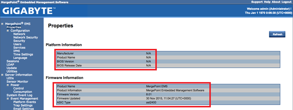
Start out by going to the IP address for MP-EMS site. From the initial display screen, we can see the MP-EMS Firmware versions but not the Platform (or Mobo) BIOS Version. Why not you may ask? Well, the MP-EMS will only display Mobo information when the Mobo is powered on. Before you power on your Mobo I would recommend opening the vKVM session so that you can see the boot screen. When you power on your mobo (MP-EMS > Power > Control > Power On ) use the vKVM screen to halt at the ‘boot menu’ or even go into setup and disable all the boot devices.
In this PIC, we can see my Firmware for the MP-EMS is 8.01 and the BIOS is blank as the Mobo is not powered on.
2- Selecting the Mobo BIOS Update
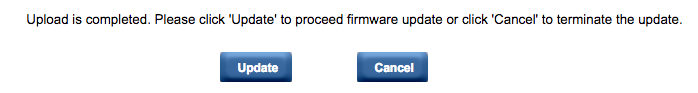
I choose the following to update the Mobo BIOS. Start out by uploading the file: Update > ‘BIOS & ME’ > Choose File > Image.RBU > Upload

Once the upload is complete, click on ‘Update’ to proceed. NOTE: a warning dialog box appeared for me stating the system would be powered off to update the BIOS. Good thing I’m in the Boot Menu as the system will just directly power off with no regard of the system state
3 – Installing the Mobo BIOS Update: Be Patient for the BIOS install to complete
Once I saw the message the ‘BIOS firmware image has been updated successfully’ I then exited the browser session and vKVM . Note: I’d recommend closing the browser out entirely and then reopening a new session.

Once I restarted my vKVM and MP-EMS sessions and then powered on my Mobo. This allowed the BIOS update to continue.
Here is the patience part – My system was going from BIOS F01 > F10 and it rebooted 2 times to complete the update. Be patient it will complete.
Here is the behavior I noted:
- First Reboot – The system posted normally, it cleared the screen, and then white text stated a warning message about the BIOS booted to default settings. Very shortly after it rebooted again.
- On the 2nd reboot, it posted normally and I pressed F10 to get back to the Boot menu. I did this because next, we’ll need to update the MP-EMS firmware.
Once the system had rebooted I then refreshed my MP-EMS screen and viola there it was BIOS Version F10.

** Note – Not every time but sometimes, I would notice the MP-EMS Screen would show the old BIOS Version #. However, in BIOS the updated BIOS Version # would be present. A cold boot didn’t always fix this, but eventually the MP-EMS would update and would reflect the correct BIOS #**
4 – Selecting the MP-EMS Firmware
While the Mobo is booted and I’m in the boot menu, I went into the MP-EMS session and choose the following Update > BMC > Choose File > 841.img > upload
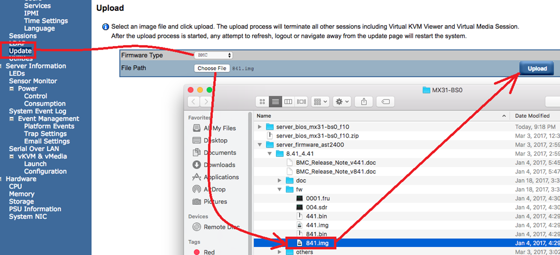
5 – Installing the MP-EMS firmware update
Once the file was uploaded I could see the Current and New versions. I then choose Update button which promptly disconnected my vKVM session and Status changed from None to a % Completed.
Again, be patient and allow the system to update. For my systems the % Complete seemed to hang a few times but the total process, for me, took about 10 mins.

After the update was complete, the next screen let me know the update was successful, my system did an auto-reboot. When I heard my system beep I then closed my MP-EMS session and started a new browser session.

Shortly after the system booted I went into the MP-EMS and validated the firmware was now 8.41.

Wrapping this up…
Ever heard the saying “It really is a simple process we just make it complicated”? Recent BIOS updates and overall system management sometimes feel this way when trying to do simple processes. Not trying to date myself but BIOS/Firmware updates have been around for decades now. I’ve done countless updates where it was simply extracting an update to simple media and then it completes the update on its own. Now one could argue that systems are more complicated and local boot devices don’t scale well for large environments and I’d say both are very true but that doesn’t mean the process can’t be made more simple.
My recommendation to firmware / bios manufactures — invest in simplicity or make it a requirement for your suppliers. You’ll have happier customers, less service calls, and more $$ in your pocket but then again if you do, what would I have to blog about?
Am I happy with the way I have to update this Mobo? Yes, I am happy with it. For the price I paid it’s really nice to have a headless environment that I can remotely update. I won’t have to do it very often so I’m glad I wrote down my steps in this blog.
If you like my ‘no-nonsense’ blog articles that get straight to the point… then post a comment or let me know… Else, I’ll start writing boring blog content.
Home Lab Gen IV – Part III: Best ESXi White box Mobo yet?
Initially, when I decided to refresh my Home Lab to Generation IV I planned to wipe just the software and add InfiniBand. I would keep most of the hardware. However, as I started to get into this transformation I decided it was time for a hardware refresh too including moving to All Flash vSAN.
In this post, I wanted to write a bit more about my new motherboard (mobo) and why I think it’s a great choice for a home lab. The past workhorse of my home lab has been my trusty MSI Z68MS-G45(B3) Rev 3.0 (AKA MSI-7676). I bought 3 MSI-7676 in 2012 and this mobo has been a solid performer and they treated me very well. However, they were starting to age a bit so I sold them off to a good buddy of mine and I used those resources to fund my new items.
My new workhorse –
Items kept from Home Lab Gen III:
- 3 x Antec Sonata Gen I and III each with 500W PS by Antec: I’ve had one of these cases since 2003, now that is some serious return on investment
New Items:
- 3 x Gigabyte MX31-BS0 – So feature rich, I found them for $139 each, and this is partly why I feel it’s the best ESXi white box mobo
- 3 x Intel Xeon E3-1230 v5 – I bought the one without the GPU and saved some $$
- 3 x 32GB DDR4 RAM – Nothing special here, just 2133Mhz DDR4 RAM
- 3 x Mellanox Connectx InfiniBand cards (More to come on this soon)
- 4 x 200GB SSD, 1 x 64GB USB (Boot)
- 1 x IBM M5210 JBOD SAS Controller
Why I chose the Gigabyte MX31-BS0 –
Likes:
- Headless environment: This Mobo comes with an AST2400 headless chipset environment. This means I no longer am tied to my KVM. With a java enabled browser, I can view the host screen, reboot, go into BIOS, BIOS updates, view hardware, and make adjustments as if I was physically at the box
- Virtual Media: I now can virtually mount ISOs to the ESXi host without directly being at the console (Still to test ESXi install)
- Onboard 2D Video: No VGA card needed, the onboard video controller takes care of it all. Why is this important? You can save money by choosing a CPU that doesn’t have the integrated GPU, the onboard video does this for you
- vSphere HCL Support: Really? Yep, most of the components on this mobo are on the HCL and Gigabyte lists ESXi 6 as a supported OS, its not 100% HCL but for a white box its darn close
- Full 16x PCIe Socket: Goes right into the CPU << Used for the Infiniband HCA
- Full 8x PCIe Socket: Goes into the C232 << Used for the IBM M5210
- M.2 Socket: Supporting 10Gb/s for SSD cards
- 4 x SATA III ports (white)
- 2 x SATA III can be used for Satadom ports (orange) with onboard power connectors
- 2 x Intel i210 1Gbe (HCL supported) NICs
- E3 v5 Xeon Support
- 64GB RAM Support (ECC or Non-ECC Support)
- 1 x Onboard USB 2.0 Port (Great for a boot drive)
Dislikes: (Very little)
- Manual is terrible
- Mobo Power connector is horizontal with the mobo, this made it a bit tight for a common case
- 4 x SATA III Ports (White) are horizontal too, again hard to seat and maintain
- No Audio (Really not needed, but would be nice)
- For some installs, it could be a bit limited on PCIe Ports
Some PICS :
The pic directly below shows 2 windows: Window 1 has the large Gigabyte logo, this is the headless environmental controls. From here you can control your host and launch the video viewer (window 2). The video viewer allows you to control your host just as if you were physically there. In windows 2 I’m in the BIOS settings for the ESXi host.

This is a stock photo of the MX31-BS0. It’s a bit limited on the PCIe ports, however, I don’t need many ports as soon I’ll have 20Gb/s InfiniBand running on this board but that is another post soon to come!

If you like my ‘no-nonsense’ blog articles that get straight to the point… then post a comment or let me know… Else, I’ll start writing boring blog content.
VSAN – Setting up VSAN Observer in my Home Lab
VSAN Observer is a slick way to display diagnostic statics not only around how the VSAN is performing but how the VM’s are as well.
Here are the commands I entered in my Home Lab to enable and disable the Observer.
Note: this is a diagnostic tool and should not be allowed to run for long periods of time as it will consume many GB of disk space. Ctrl+C will stop the collection
How to Start the collection….
- vCenter239:~ # rvc root@localhost << Logon into vCenter Server Appliance | Note you may have to enable SSH
- password:
- /localhost> cd /localhost/Home.Lab
- /localhost/Home.Lab> cd computers/Home.Lab.C1 << Navigate to your cluster | Mine Datacenter is Home.Lab, and cluster is Home.Lab.C1
- /localhost/Home.Lab/computers/Home.Lab.C1> vsan.observer ~/computers/Home.Lab.C1 –run-webserver –force << Enter this command to get things started, keep in mind double dashes “—” are used in front of run-webserver and force
- [2014-09-17 03:39:54] INFO WEBrick 1.3.1
- [2014-09-17 03:39:54] INFO ruby 1.9.2 (2011-07-09) [x86_64-linux]
- [2014-09-17 03:39:54] WARN TCPServer Error: Address already in use – bind(2)
- Press <Ctrl>+<C> to stop observing at any point ...[2014-09-17 03:39:54] INFO WEBrick::HTTPServer#start: pid=25461 port=8010 << Note the Port and that Ctrl+C to stop
- 2014-09-17 03:39:54 +0000: Collect one inventory snapshot
- Query VM properties: 0.05 sec
- Query Stats on 172.16.76.231: 0.65 sec (on ESX: 0.15, json size: 241KB)
- Query Stats on 172.16.76.233: 0.63 sec (on ESX: 0.15, json size: 241KB)
- Query Stats on 172.16.76.232: 0.68 sec (on ESX: 0.15, json size: 257KB)
- Query CMMDS from 172.16.76.231: 0.74 sec (json size: 133KB)
- 2014-09-17 03:40:15 +0000: Live-Processing inventory snapshot
- 2014-09-17 03:40:15 +0000: Collection took 20.77s, sleeping for 39.23s
- 2014-09-17 03:40:15 +0000: Press <Ctrl>+<C> to stop observing
How to stop the collection… Note: the collection has to be started and running to web statics as in the screenshots below
- ^C2014-09-17 03:40:26 +0000: Execution interrupted, wrapping up … << Control+C is entered and the observer goes into shutdown mode
- [2014-09-17 03:40:26] INFO going to shutdown …
- [2014-09-17 03:40:26] INFO WEBrick::HTTPServer#start done.
- /localhost/Home.Lab/computers/Home.Lab.C1>
How to launch the web interface…
I used Firefox to logon to the web interface of VSAN Observer, IE didn’t seem to function correctly
Simply go to http://[IP of vCenter Server]:8010 Note: this is the port number noted above when starting and its http not https
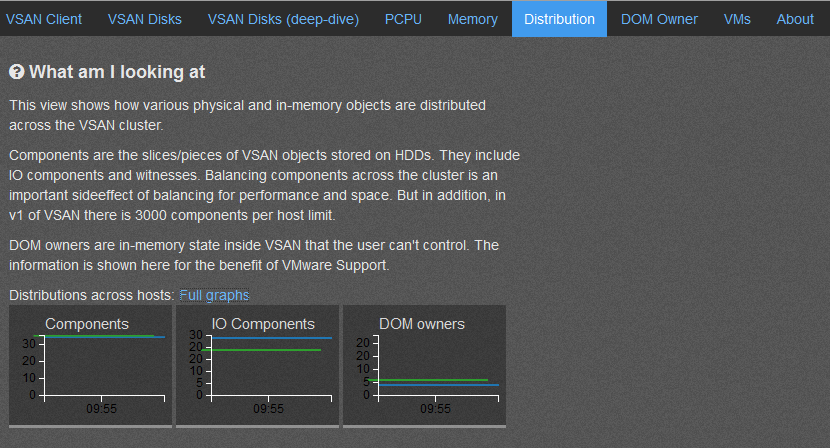
So what does it look like and what is the purpose of each screen… Note: By Default the ‘? What am I looking at’ is not displayed, I expanded this view to enhance the description of the screenshot.


References:
http://www.yellow-bricks.com/2013/10/21/configure-virtual-san-observer-monitoring/
Home Lab – Adding freeNAS 8.3 iSCSI LUNS to ESXi 5.1
About a half a year ago I setup my freeNAS iSCSI SAN, created 2 x 500GB iSCSI LUNS and attached them to ESXi 5.1. These were ample for quite a while. However I have the need to add additional LUNS…. My first thought was – “Okay, Okay, where are my notes on adding LUNS…” They are non-existent… Eureka! Its time for a new blog post… So here are my new notes around adding iSCSI LUNS with freeNAS to my ESXi 5.1 Home lab – As always read and use at your own risk
J
- Start in the FreeNAS admin webpage for your device. Choose Storage > Expand Volumes > Expand the volume you want to work with > Choose Create ZFS volume and fill out the Create Volume Pop up.

When done click on Add and ensure is show up under the Storage Tab
. 
-
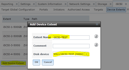
On the left-hand pane click on Services > iSCSI > Device Extents > View Device Extents. Type in your Extent Name, Choose the Disk Device that you just created in Step 1 and choose OK
-
Click on Associated Targets > Add Extent to Target, Choose your Target and select the new Extent

-
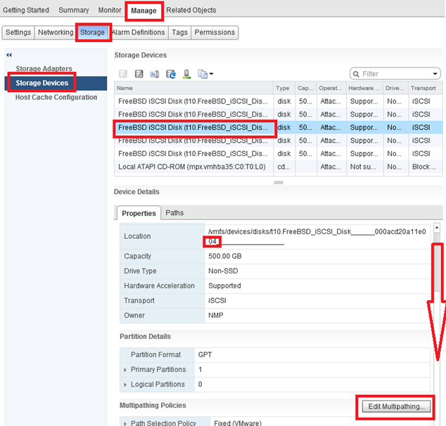
To add to ESXi do the following… Log into the Web Client for vCenter Server, Navigate to a host > Manage > Storage > Storage Devices > Rescan Host
If done correctly your new LUN should show up below. TIP – ID the LUN by its location number, in this case its 4

-
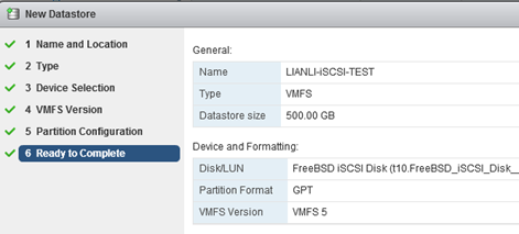
Ensure your on the Host in the left Pane > Related Objects > Datastores > Add Datastore

-
Type in the Name > VMFS Type > Choose the Right LUN (4) > VMFS Version (5) > Partition Lay out (All or Partial), Review > Finish
-
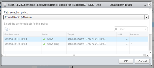
Setup Multi-Pathing – Select a Host > Manage > Storage > Storage Devices > Select LUN > Slide down the Devices Details Property Box and Choose Edit Multipathing
-
Choose Round Robin and Click On Okay
-
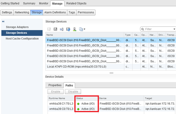
Validate all Datastores still have Round Robin enabled. 2 Ways to do this.
- Click on the LUN > Paths. Status should read Active I/O for both paths
- Click on LUN > Properties > Edit Multipathing – Path section Policy should state – Round Robin (See PIC in Step 8)
Summary – These steps worked like a charm for me, then again my environment is already setup, and hopefully these steps might be helpful to you.
ESXi Q&A Boot Options – USB, SD, & HD
Here are some of my notes around boot options for ESXi.
The post covers a lot of information especially around booting to SD or USB.
Enjoy!
What are the Options to install ESXi?
- Interactive ESXi Installation
- Scripted ESXi Installation
- vSphere Auto Deploy ESXi Installation Option – vSphere 5 Only
- Customizing Installations with ESXi Image Builder CLI – vSphere 5 Only
What are the boot media options for ESXi Installs?
The following boot media are supported for the ESXi installer:
- Boot from a CD/DVD
- Boot from a USB flash drive.
- PXE boot from the network. PXE Booting the ESXi Installer
-
Boot from a remote location using a remote management application.
What are the acceptable targets to install/boot ESXi to and are there any dependencies?
ESXi 5.0 supports installing on and booting from the following storage systems:
-
SATA disk drives – SATA disk drives connected behind supported SAS controllers or supported on-board SATA controllers.
- Note -ESXi does not support using local, internal SATA drives on the host server to create VMFS datastores that are shared across multiple ESXi hosts.
- Serial Attached SCSI (SAS) disk drives. Supported for installing ESXi 5.0 and for storing virtual machines on VMFS partitions.
- Dedicated SAN disk on Fibre Channel or iSCSI
- USB devices. Supported for installing ESXi 5.0. For a list of supported USB devices, see the VMware Compatibility Guide at http://www.vmware.com/resources/compatibility.
Storage Requirements for ESXi 5.0 Installation
- Installing ESXi 5.0 requires a boot device that is a minimum of 1GB in size.
- When booting from a local disk or SAN/iSCSI LUN, a 5.2GB disk is required to allow for the creation of the VMFS volume and a 4GB scratch partition on the boot device.
- If a smaller disk or LUN is used, the installer will attempt to allocate a scratch region on a separate local disk.
- If a local disk cannot be found the scratch partition, /scratch, will be located on the ESXi host ramdisk, linked to /tmp/scratch.
-
You can reconfigure /scratch to use a separate disk or LUN. For best performance and memory optimization, VMware recommends that you do not leave /scratch on the ESXi host ramdisk.
- To reconfigure /scratch, see Set the Scratch Partition from the vSphere Client.
- Due to the I/O sensitivity of USB and SD devices the installer does not create a scratch partition on these devices. As such, there is no tangible benefit to using large USB/SD devices as ESXi uses only the first 1GB.
- When installing on USB or SD devices, the installer attempts to allocate a scratch region on an available local disk or datastore.
- If no local disk or datastore is found, /scratch is placed on the ramdisk. You should reconfigure /scratch to use a persistent datastore following the installation.
10 Great things to know about Booting ESXi from USB – http://blogs.vmware.com/esxi/2011/09/booting-esxi-off-usbsd.html <<< This is worth a read should clear up a LOT of questions….
How do we update a USB Boot Key?
It would follow the same procedure as any install or upgrades, to the infrastructure it acts all the same.
Can an ESXi Host access USB devices ie. Can an External USB Hard Disk be connected directly to the ESXi Host for copying of data?
- Yes this can be done, see the KB below – ‘Accessing USB storage and other USB devices from the service console’
- However the technology that supports USB device pass-through from an ESX/ESXi host to a virtual machine does not support simultaneous USB device connections from USB pass-through and from the service console.
- This means the host is in either Pass Through (to the VM) or service console mode.
References –
vSphere 5 Documentation Center (Mainly Under ‘vSphere Installation and Setup’)
Installing ESXi Installable onto a USB drive or SD flash card
USB support for ESX/ESXi 4.1 and ESXi 5.0
VMware support for USB/SD devices used for installing VMware ESXi
Installing ESXi 5.0 on a supported USB flash drive or SD flash card
Accessing USB storage and other USB devices from the service console
Update to my Home Lab with VMware Workstation 8 – Part 2 Fun with a Windows 7 Installer
Part 1 of this series outlined the hardware I wanted to purchase and some of the ideas I had around the products.
I created an image of the current install of Windows 7, then booted it to my new hardware, and to my surprise there were not any hidden files or drivers that needed adjusted.
It worked quite well, so well it was scary but simply Impressive…. Sure beats those old XP days when you had to just about tear it apart to get it to work.
However I would like this install of Workstation 8 to run on a fresh copy of Windows 7 so I have decided to reinstall it.
Now this shouldn’t warrant a blog post however they way I had to get Windows 7 to behave is why I’m posting.
In this post I go into getting Windows 7 to install properly when you don’t have proper installation CD.
The CD I own for Windows 7 is an Windows based Installation only, you cannot create boot CD to install the OS fresh.
Trust me I tired many ways but it just doesn’t work…
Here is what I wanted to accomplish –
1. I’d like a fresh copy of Windows 7 Installed on to my system
2. I need to enable AHCI in my system BIOS (for more info see here http://en.wikipedia.org/wiki/Advanced_Host_Controller_Interface)
I found on the corsair blogs that my SSD drive will run much better if you enable AHCI in your BIOS.
Unfortunately this pretty much deems a reinstall. I’m okay with this because it is what I’m wanting to do.
Issues –
1. The version of Windows 7 I have is an upgrade or restore only version.
2. Currently AHCI is not enabled in my BIOS
Here’s how I did it… Oh, did it take some trickery and learning but it worked..
Know this…
Windows 7 will do a recovery install to your current HD (C:) or to a new HD (E:).
If you install to your current HD, C:, then it will install in to a WINDOWS.001 folder, and leave lots of old files laying around.
Not ideal as I want a pristine Install
Do this…
From Windows I initiated the install, choose custom install and choose my E: drive (At the time E: was just a blank HD)

Windows did it typical install, Copying files, and they rebooted the system.
During the reboot I enabled AHCI on ALL controllers in the BIOS << THIS IS VERY important step, if you miss this Windows will install in IDE Mode
Windows completed the install and boots to your E: drive.
Having E:\ be the boot and E:\Windows is not ideal. I really want Windows 7 on my C: drive.
I formatted my C: drive and ran the windows install, only this time choose the C: HD.
Windows completes the install and reboots.
When I was done Windows 7 is a fresh install and running on the C: drive.
Summary…
I got to tell you it was a chore figuring this out, it seems very simple now but I went through imaging processes, partition changing, drive renames, lots of blog posts, KB’s, etc…
Nothing worked well and it took up hours of my time. This pattern worked for me, Windows 7 installed properly and its working quite well.
Now its on to installing Workstation 8…
